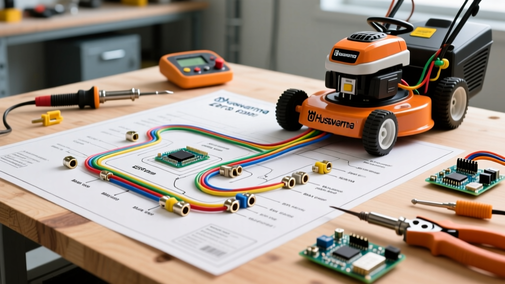

The Critical Intersection of 12V DC Systems and Operator Safety
When servicing or modifying outdoor power equipment, reading a wiring diagram for Husqvarna zero turn mower models is not merely an exercise in restoring electrical function; it is a strict adherence to life-safety protocols. Modern zero-turn mowers, such as the popular Husqvarna Z254 and MZ61, utilize complex 12V DC networks that integrate high-amperage starter circuits with low-amperage solid-state safety interlocks. A misunderstood ground path or an improperly bypassed seat switch doesn't just result in a no-start condition—it can lead to catastrophic laceration hazards or electrical fires.
According to the U.S. Consumer Product Safety Commission (CPSC), riding mower incidents frequently involve unintended movement and blade engagement. This makes strict adherence to the Outdoor Power Equipment Institute (OPEI) ANSI/OPEI B71.4 safety standards non-negotiable for DIYers and professional technicians alike. This guide dissects the anatomy of Husqvarna's electrical schematics through the lens of safety and code compliance.
WARNING: Never bypass operator presence control (OPC) switches. Bypassing the seat switch or PTO interlock violates federal safety standards and voids manufacturer warranties, creating severe runaway and amputation hazards.
Decoding the Interlock Logic Matrix
The core of any Husqvarna zero-turn schematic is the safety interlock matrix. Unlike older tractors that relied on simple series wiring, modern Husqvarna mowers use a combination of SPDT (Single Pole Double Throw) microswitches and time-delay relays to monitor operator presence. When analyzing your wiring diagram for Husqvarna zero turn mower configurations, you will typically encounter four primary safety nodes:
- Seat Switch: Detects operator weight. If the PTO (blade) is engaged and the operator leaves the seat, the relay cuts ignition ground, killing the engine within 0.5 seconds.
- PTO (Blade Engagement) Switch: A heavy-duty toggle or dash switch that triggers the PTO clutch relay. The schematic will show this routed through the brake/steering lever interlocks to prevent blade engagement during cranking.
- Steering Lever / Brake Switches: Zero-turns utilize lap bars. The wiring diagram shows switches at the base of the lap bars. If the bars are not in the neutral/parked position, the starter solenoid ground circuit remains open.
- Ignition Switch: Acts as the master gate, routing 12V to the ignition module and the accessory/PTO bus.
Table: Typical Husqvarna Interlock Switch States
| Component | Normal State (Unactuated) | Actuated State (Safe to Operate) | Wire Gauge (Typical) |
|---|---|---|---|
| Seat Switch | Normally Open (NO) | Closed (Completes Ground) | 18 AWG |
| Lap Bar / Brake | Normally Closed (NC) | Open (Breaks Ground to Kill) | 16 AWG |
| PTO Clutch Switch | Normally Open (NO) | Closed (Sends 12V to Relay) | 14 AWG |
Wire Gauge Compliance and Routing Standards
Automotive and outdoor power equipment wiring must comply with SAE J1128 standards for low-tension primary cable. A common failure mode in zero-turn mowers is harness chafing against the hydrostatic transmission pumps or the mower deck suspension. When repairing a harness based on your wiring diagram for Husqvarna zero turn mower systems, matching the correct American Wire Gauge (AWG) is critical to prevent voltage drop and thermal runaway.
AWG Sizing and Overcurrent Protection
Using undersized wire for high-draw components like the starter motor or the PTO clutch will cause the insulation to melt, potentially igniting dry grass clippings accumulated under the chassis. Below is the strict gauge and fusing matrix required for safe Husqvarna repairs:
- Battery to Starter Solenoid: 4 AWG or 6 AWG (Stranded Copper). Unfused on the main positive lug in many OEM designs, but protected by the main 30A/40A inline fuse near the battery positive terminal.
- Solenoid to Starter Motor: 4 AWG. Must be routed away from the engine exhaust manifold.
- PTO Clutch Circuit: 12 AWG or 14 AWG. The PTO clutch (often an Ogura or Warner Electric model drawing 3.5A to 5A steady-state) experiences an inrush current of up to 12A upon engagement. Therefore, the wiring diagram will specify a 20A ATO blade fuse. Never downgrade this to a 10A fuse, or it will blow on every blade engagement.
- Ignition and Safety Switches: 16 AWG or 18 AWG. Protected by a 5A or 7.5A inline fuse.
Environmental Sealing and IP Ratings
Zero-turn mowers operate in highly corrosive environments: high humidity, direct UV exposure, mud, and acidic grass sap. The Husqvarna technical support documentation emphasizes the use of sealed connectors in their modern wiring harnesses. When replacing a damaged pigtail or repairing a chewed wire (a common issue if rodents nest in the winterized mower), you must maintain the IP67 environmental rating of the circuit.
Best Practices for Environmental Compliance:
- Heat Shrink with Adhesive: Never use standard electrical tape for outdoor mower wiring. UV rays and vibration will peel the adhesive within weeks. Use dual-wall, adhesive-lined marine-grade heat shrink tubing.
- Dielectric Grease: Apply a silicone-based dielectric grease to all multi-pin connectors, especially the 2-pin PTO clutch connector located beneath the chassis. This prevents water ingress and galvanic corrosion on the copper terminals.
- Split Loom Tubing: Any wire routed near the hydrostatic drive belts or the deck lift linkages must be encased in flexible nylon split loom and secured with UV-resistant zip ties, leaving a minimum 2-inch clearance from moving parts.
Diagnostic Troubleshooting: Testing vs. Bypassing
A dangerous trend in DIY lawn care is the use of jumper wires to 'bypass' a faulty seat switch or brake switch to keep the mower running. This is a severe safety violation. Instead, use a digital multimeter (DMM) to diagnose the exact failure point in the wiring diagram for Husqvarna zero turn mower circuits.
Step-by-Step Safe Diagnostic Flow
- Disconnect the Battery: Always remove the negative (-) terminal first before probing the wiring harness to prevent accidental shorting across the frame.
- Set DMM to Continuity/Ohms: Locate the suspected switch (e.g., the right lap bar neutral switch).
- Probe the Terminals: With the lever in the parked position, check for continuity. If the schematic indicates a Normally Closed (NC) switch for the safety ground, your meter should read near 0.0 ohms. If it reads 'OL' (Open Loop), the internal microswitch has failed.
- Check for Voltage Drop: Reconnect the battery, turn the key to 'ON' (engine off), and set the DMM to DC Volts. Probe the PTO clutch connector. If you read 11.5V or higher but the clutch won't engage, the electrical circuit is fine, and the mechanical clutch air gap (typically 0.018 to 0.022 inches) requires adjustment.
Summary of Code-Compliant Maintenance
Treating the electrical system of your outdoor power equipment with the same rigor as household AC wiring is the hallmark of a professional. By strictly following the OEM wiring diagram for Husqvarna zero turn mower models, utilizing SAE-compliant wire gauges, and respecting the ANSI/OPEI safety interlock logic, you ensure that your machine operates reliably and safely for years to come. Always source OEM replacement relays and harnesses, as aftermarket knock-offs frequently lack the internal diode suppression required to protect the mower's solid-state ignition modules from voltage spikes.