
The Anatomy of a 12V Appliance Lighting Circuit
Integrating low-voltage lighting into kitchen appliances, under-cabinet spaces, and toe-kick zones requires a fundamental shift from standard 120V AC residential wiring. When searching for a reliable wiring diagram for LED lights in appliance applications, the primary challenge is not just connecting wires, but managing the conversion from high-voltage alternating current (AC) to low-voltage direct current (DC). As of 2026, high-density LED tape lights (like the WAC Lighting InvisiLED Pro 2) draw significantly more power per foot than older generations, making precise transformer sizing and voltage drop mitigation critical to preventing thermal throttling and premature diode failure.
This guide provides an expert-level breakdown of the wiring diagram for LED lights specifically tailored for appliance and cabinetry integration. We will cover component selection, NEC compliance, and exact troubleshooting protocols for the most common failure modes encountered in the field.
Core Components & 2026 Pricing Matrix
Before executing the wiring diagram for LED lights, you must source components that communicate correctly. Mismatched dimmers and drivers are the leading cause of flickering in appliance lighting. Below is a curated bill of materials (BOM) based on current 2026 market pricing and field reliability.
| Component Category | Recommended Model (2026) | Specifications | Est. Cost |
|---|---|---|---|
| Power Supply (Driver) | Mean Well XLG-150-H-AB | 150W, 12V DC, IP67 Rated, Dimmable | $74.00 |
| Dimmer Switch | Lutron Diva DVELV-300P | Electronic Low Voltage (ELV), 300W Max | $48.50 |
| LED Tape Light | WAC InvisiLED Pro 2 | 24V DC, 4.4W/ft, CRI 90+ | $14.00/ft |
| Wire Connectors | WAGO 221-413 Lever Nuts | 3-Conductor, 24-12 AWG, 600V | $0.65/ea |
| DC Wiring | Southwire 12 AWG Stranded | 2-Conductor, Red/Black, THHN | $0.85/ft |
Note: If you are using 24V DC LED strips (which we highly recommend for runs over 15 feet to minimize voltage drop), ensure your Mean Well driver is set to the 24V output model (e.g., XLG-150-H-B).
The Wiring Diagram for LED Lights: Step-by-Step Flow
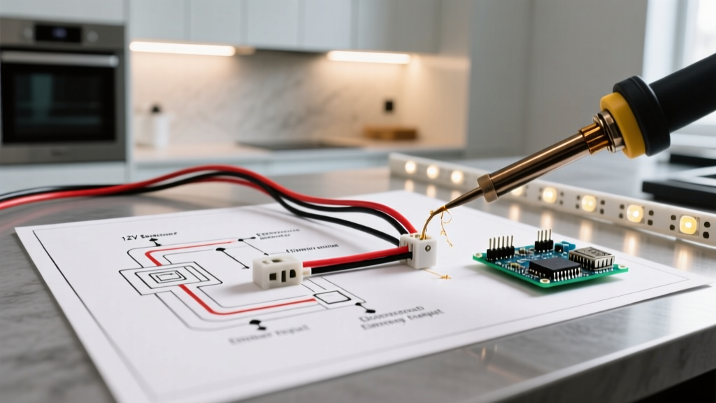
The following sequence outlines the physical wiring diagram for LED lights from the breaker panel to the final LED node. Always verify power is off at the main breaker using a non-contact voltage tester (like the Klein Tools NCVT-4IR) before beginning.
Phase 1: 120V AC Mains to the Dimmer
- Run 14/2 NM-B Cable: Route a dedicated 14/2 Romex cable from a 15A kitchen lighting breaker to the wall switch box. According to the NFPA NEC guidelines, kitchen lighting circuits must be separate from small-appliance receptacle circuits.
- Terminate at the Dimmer: Connect the bare copper ground to the green ground screw on the Lutron DVELV-300P. Connect the white neutral wire to the silver neutral screw, and the black hot wire to the brass line-in screw. Cap any unused wires with WAGO connectors.
Phase 2: Dimmer to the LED Driver (Transformer)
- Run 14/2 NM-B to the Cabinet: Route the switched hot (load) and neutral from the dimmer to the hidden cabinet cavity where the Mean Well driver will be mounted.
- AC Input Termination: On the Mean Well XLG series, connect the incoming black (switched hot) to the brown AC wire, and the incoming white (neutral) to the blue AC wire. Connect the bare ground to the yellow/green ground wire. Secure all connections using closed-end crimp connectors or WAGO lever nuts, then tuck them into a junction box to meet NEC Article 314 requirements.
Phase 3: 12V/24V DC Output to the LED Strips
- DC Output Termination: The Mean Well driver outputs DC power via red (V+) and black (V-) wires. Strip 1/2 inch of insulation and connect these to your 12 AWG stranded DC trunk wire.
- Route to the Aluminum Channel: Run the 12 AWG DC wire through the back of the cabinet to the underside where the aluminum extrusion channel is mounted.
- Solderless LED Connection: Use a proprietary quick-connector (like the WAC X-2 connector) or solder the DC trunk wire directly to the copper pads on the LED tape light. Soldering provides a superior mechanical bond that resists thermal expansion vibrations from nearby appliances like dishwashers and range hoods.
Voltage Drop Matrix & Wire Gauge Selection
A critical flaw in many online guides is the failure to account for DC voltage drop. Unlike 120V AC, a 10% drop on a 12V DC line leaves you with 10.8V, which will cause the LEDs to flicker, shift color temperature, or fail to illuminate entirely. The U.S. Department of Energy notes that maintaining optimal voltage is essential for LED efficacy and lifespan.
Use the matrix below to select the correct DC trunk wire gauge based on your total wattage and run length from the driver to the furthest LED node.
| Total LED Wattage | Run Length (Under 10 ft) | Run Length (10 - 20 ft) | Run Length (20 - 30 ft) |
|---|---|---|---|
| Under 30W | 16 AWG | 14 AWG | 12 AWG |
| 30W - 60W | 14 AWG | 12 AWG | 10 AWG |
| 60W - 100W | 12 AWG | 10 AWG | 8 AWG |
Pro-Tip: For runs exceeding 25 feet, always transition to a 24V DC system. The current draw (Amperage) is halved at 24V compared to 12V for the same wattage, drastically reducing resistive heat and voltage drop.
Dimmer Topology: Why TRIAC Fails and ELV Wins
When interpreting a wiring diagram for LED lights, the dimmer topology is where most DIYers fail. Standard incandescent dimmers use leading-edge TRIAC phase-cut dimming. When applied to the internal capacitors of an LED driver, TRIAC dimmers cause inrush current spikes, resulting in an audible buzzing from the transformer and visible strobing at low dim levels.
For appliance cabinet lighting, you must use an Electronic Low Voltage (ELV) dimmer, which utilizes trailing-edge phase-cut dimming. The Lutron DVELV-300P specified in our BOM is an ELV dimmer. It smoothly bleeds off the trailing edge of the AC sine wave, which the Mean Well driver's internal rectifier can process cleanly, resulting in smooth, flicker-free dimming down to 1%.
NEC Code Compliance for Kitchen & Appliance Wiring
Code Alert (NEC 2023/2026 Cycle): Any 120V AC wiring routed within 6 feet of a kitchen sink or wet bar area must be protected by a Ground Fault Circuit Interrupter (GFCI). If your under-cabinet lighting circuit shares a line with countertop receptacles, the entire circuit must be GFCI protected at the breaker or the first receptacle.
Furthermore, the low-voltage DC side of your wiring diagram for LED lights falls under NEC Article 725 (Class 2 and Class 3 Remote-Control, Signaling, and Power-Limited Circuits). Class 2 circuits (under 100W and under 30V) do not require the DC wires to be run inside metal conduit or behind drywall, provided you are using CL2-rated (Class 2) insulated wire. However, the 120V AC side must be properly secured to framing members with cable staples within 8 inches of the junction box, per Article 334.
Troubleshooting Edge Cases & Failure Modes
Even with a perfect wiring diagram for LED lights, environmental factors in kitchens can introduce anomalies. Here is how to diagnose the three most common edge cases:
- Ghosting (LEDs glow faintly when off): This occurs when an incompatible smart switch or dimmer with an internal neon locator light leaks a micro-current through the circuit to power its own internal Wi-Fi radio. Fix: Install a Lutron LUT-MLC (Minimum Load Capacitor) across the load and neutral at the transformer, or switch to a dimmer that requires a dedicated neutral wire to power its internal logic.
- Thermal Throttling at the Driver: If the Mean Well driver is mounted flat against the top of a wooden cabinet directly above a stove or dishwasher, the ambient heat will trigger the driver's internal thermal protection, causing the lights to shut off intermittently. Fix: Mount the driver vertically on a side panel with a 1-inch air gap for convective cooling, or use the IP67-rated metal-cased HLG series instead of the plastic XLG series.
- Color Shift at the End of the Run: If the LEDs near the driver are bright white (3000K) but the LEDs at the end of a 20-foot strip look yellowish and dim, you are experiencing severe voltage drop affecting the internal PWM controllers on the strip. Fix: Implement a 'home-run' wiring topology. Run separate 12 AWG DC wires from the driver to the beginning, middle, and end of the LED strip, injecting power at multiple nodes rather than daisy-chaining the entire load through the strip's internal copper traces.
Final Inspection and Energization
Before closing up your cabinet access panels, perform a continuity test on the DC trunk lines with a multimeter to ensure no stray strands of 12 AWG wire are bridging the V+ and V- terminals, which would instantly short and destroy the driver upon energization. Once cleared, restore power at the breaker, verify the dimmer's low-end trim setting (adjusting the physical dial on the Lutron switch until the lights just barely turn off), and secure your access panels. By adhering strictly to this wiring diagram for LED lights, you ensure a commercial-grade, flicker-free appliance lighting installation built to last well beyond 2026.