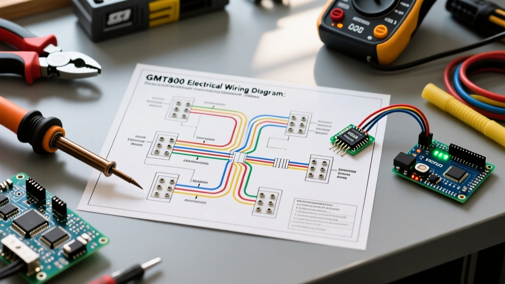

The GMT800 Platform: Legendary Trucks, Notorious Grounds
The 1999-2006 GM GMT800 platform (Chevy Silverado and GMC Sierra 1500/2500) remains one of the most popular DIY project vehicles on the road in 2026. Whether you are running a 5.3L Vortec V8 or the 6.6L Duramax, the mechanicals are virtually bulletproof. However, the electrical system tells a different story. If you own one of these trucks, you have likely experienced the infamous 'dim headlight syndrome,' flickering instrument cluster gauges, or erratic blower motor behavior.
Before you start throwing expensive parts like alternators or Body Control Modules (BCMs) at the truck, you must consult the factory electrical wiring diagram. In 90% of GMT800 electrical gremlins, the root cause is not a failed component, but a degraded ground circuit. This vehicle-specific guide will walk you through decoding the GM front lighting harness, identifying the critical ground nodes, and executing a permanent, dealership-level repair using modern diagnostic protocols.
Decoding the GMT800 Front Lighting Harness
Unlike modern vehicles that rely heavily on CAN-bus multiplexing for exterior lighting, the GMT800 uses a traditional, relay-switched analog circuit. Power flows from the underhood fuse block (UBEC) through the headlight relays, down to the multifunction switch, and out to the bulbs. However, the return path—the ground circuit—is where GM engineers made a critical flaw. They routed multiple high-amperage ground wires to painted steel fender wells using star washers, a recipe for galvanic corrosion.
GM Standard Wire Color Matrix (Front Lighting)
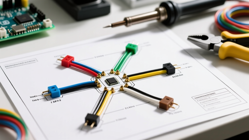
When tracing faults with a multimeter, you must match the physical wire colors to the factory schematic. Below is the definitive color code reference for the GMT800 front headlight harness:
| Circuit Function | Wire Color | Wire Gauge | Destination |
|---|---|---|---|
| Right High Beam | Dark Green | 16 AWG | Headlight Bulb Pin 3 |
| Right Low Beam | Yellow | 16 AWG | Headlight Bulb Pin 1 |
| Left High Beam | Tan | 16 AWG | Headlight Bulb Pin 3 |
| Left Low Beam | Light Green | 16 AWG | Headlight Bulb Pin 1 |
| Headlight Ground | Black | 14 AWG | Node G100 / G102 |
The 'Black Death' Failure Mode: Nodes G100 and G102
In the GM electrical wiring diagram, the front lighting grounds are designated as G100 (Left Front Fender) and G102 (Right Front Fender). These nodes are located deep inside the fender wells, directly behind the battery tray on the driver's side and the airbox on the passenger side.
Over two decades of exposure to road salt, water intrusion, and thermal cycling, the copper ring terminals oxidize against the steel chassis. This creates a high-resistance connection. According to SAE J1128 standards for automotive low-voltage cables, any connection introducing resistance above 0.1 ohms will cause a measurable voltage drop, starving the halogen or upgraded LED bulbs of necessary current.
Expert Insight: Never simply unbolt, wire-brush, and re-tighten a GMT800 ground bolt. The factory M6x1.0 flange bolts often snap off inside the threaded chassis nut due to rust-welding. Always apply penetrating fluid (like PB Blaster) 24 hours before attempting removal, and have an M6x1.0 thread chaser on standby.
Step-by-Step Ground Relocation and Harness Rebuild
To permanently fix the G100/G102 ground issues, we recommend bypassing the factory fender-well locations entirely and relocating the grounds to the engine block or a dedicated, easily accessible chassis bolt. Here is the exact 2026 procedure:
- Disconnect the Battery: Isolate the negative terminal. Wait 10 minutes for the BCM to enter sleep mode to prevent parasitic draw codes.
- Excise the Factory Harness: Cut the black 14 AWG ground wires approximately 6 inches from the factory harness wrap. Strip 1/2 inch of insulation.
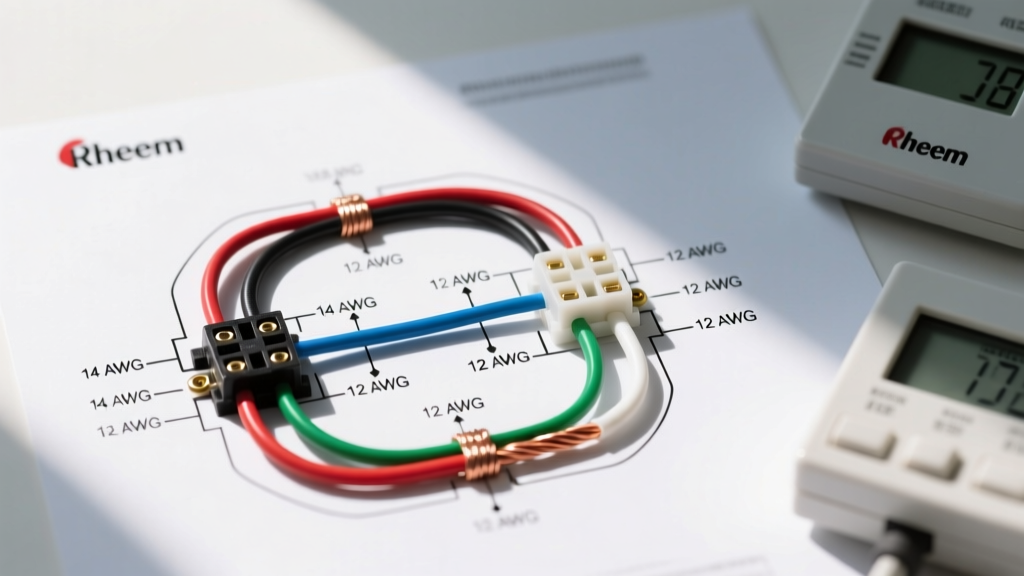
- Splice and Upgrade: Using a marine-grade heat-shrink butt connector (ancor brand), splice the factory 14 AWG wire to a new 10 AWG primary wire. Upgrading to 10 AWG reduces resistance and future-proofs the circuit if you install higher-draw auxiliary lighting.
- Terminate with Ring Terminals: Crimp a heavy-duty, tinned copper 3/8-inch ring terminal onto the new 10 AWG wire. Seal the crimp with dual-wall adhesive heat shrink.
- Prep the New Ground Point: Locate the upper engine block to chassis bellhousing bolt on the driver's side. Remove the bolt, sand the mating surface on the engine block down to bare, shiny metal using 80-grit sandpaper.
- Reassemble with Anti-Oxidant: Coat both sides of the ring terminal with Noalox (aluminum-to-copper anti-oxidant compound). Reinstall the bolt and torque to 37 lb-ft.
Diagnostic Protocol: Voltage Drop Testing
Guesswork destroys wiring harnesses. To verify your repair, you must perform a live voltage drop test. As outlined in Fluke's authoritative guide on voltage drop testing, you must measure the circuit while it is under load.
How to Execute the Test
- Set your digital multimeter (DMM) to DC Volts.
- Turn the truck's ignition to RUN and switch the headlights to LOW beam.
- Place the DMM's red probe on the battery's negative terminal (not the clamp, the actual lead post).
- Place the black probe directly on the metal casing of the headlight bulb or the back of the socket.
- The Verdict: A reading of 0.00V to 0.10V indicates a perfect ground. A reading above 0.25V confirms unwanted resistance in the ground path, meaning your G100/G102 repair was incomplete or the bulb socket itself is corroded.
2026 Diagnostic Tooling & Cost Breakdown
Working on a 20-year-old vehicle requires specific tools to prevent collateral damage to brittle harnesses. Below is a realistic cost breakdown for a professional-grade GMT800 electrical diagnostic kit in 2026:
| Tool / Part | Specific Model / Brand | 2026 Est. Price | Purpose |
|---|---|---|---|
| Digital Multimeter | Fluke 87V MAX | $450.00 | Accurate millivolt drop testing & continuity |
| Power Probe | Power Probe IV Kit | $285.00 | Instantly energize ground circuits to find breaks |
| Wire Puller | Klein Tools 56013 Fish Tape | $45.00 | Routing new 10 AWG grounds through firewall grommets |
| Pigtail Harness | Standard Motor Products S-552 | $18.50 | Replacement for melted 9005/9006 headlight sockets |
| Anti-Oxidant | Ideal Noalox 30-335 | $12.00 | Preventing galvanic corrosion at new ground nodes |
Troubleshooting Matrix: Symptoms vs. Wiring Faults
Use this quick-reference matrix to correlate your truck's specific electrical symptoms to the correct section of the electrical wiring diagram:
| Observed Symptom | Probable Wiring Fault | Diagram Node to Inspect |
|---|---|---|
| Headlights dim when blower motor is turned to High | High resistance at G110 (Engine Block Ground) | G110, Alternator Sense Wire |
| Right headlight works on High, but not Low | Corroded Yellow wire or failed multifunction switch contact | Multifunction Switch Connector C2 |
| Instrument cluster gauges sweep erratically | Bad ground at G200 (Left Kick Panel) or BCM power feed | G200, UBEC Fuse 15 |
| Parasitic battery draw over 50mA overnight | Shorted diode in alternator or stuck headlight relay | UBEC Relay 44, Alternator Pin 2 |
Frequently Asked Questions (FAQ)
Can I just add a relay harness instead of fixing the factory grounds?
Adding an aftermarket headlight relay harness (like the Putco H4 upgrade kit) is a fantastic way to deliver full battery voltage to upgraded halogen or LED bulbs. However, it does not fix the underlying GMT800 ground degradation. The relays themselves still require a solid chassis ground to trigger. If G100/G102 are corroded, your new relays will chatter or fail to engage. Fix the grounds first, then add the relay harness if desired.
Why does my GMT800 voltmeter on the dash read 14.8V, but my headlights are dim?
The dash voltmeter is wired directly to the ignition switch feed, which originates near the alternator. If the dash reads 14.8V but the headlights are dim, you have a massive voltage drop occurring after the dash cluster tap, specifically on the ground return path (G100/G102) or a corroded positive battery cable junction at the underhood fuse block (UBEC). Always trust your multimeter at the headlight socket over the factory dash gauge.
Are the GMT800 wiring diagrams available for free online?
While you can find fragmented PDF scans of the 1999-2006 GM Service Manual wiring diagrams on enthusiast forums like GMT800.com or LS1Tech, these are often low-resolution and difficult to read. For professional diagnostics, a subscription to a service like AlldataDIY or Mitchell1 provides factory-accurate, zoomable, color-coded schematics that are essential for tracing complex multiplexed circuits like the Class 2 Serial Data bus.