
Understanding 240V Electric Baseboard Heater Wiring
Wiring an electric baseboard heater requires a fundamental understanding of line-voltage circuits, pure resistance loads, and strict adherence to the National Electrical Code (NEC). Unlike forced-air furnaces that utilize 120V control circuits, standard electric baseboard heaters—such as the popular Cadet F2504W or Marley HBB series—operate directly on 240V alternating current. This configuration draws half the amperage of a 120V system for the same wattage, allowing for smaller wire gauges and more efficient power delivery over longer distances.
According to the U.S. Department of Energy, electric resistance heating is nearly 100% efficient at the point of use, making proper wiring critical to ensure safety and prevent thermal overload. In this comprehensive tutorial, we will break down the exact wire gauges, breaker sizing mathematics, and step-by-step termination procedures required for a safe, code-compliant 240V installation.
Breaker Sizing and Wire Gauge Selection Matrix
The most critical mistake DIYers make is ignoring the NEC continuous load rule. Under NEC Article 210.20(A), baseboard heaters are classified as continuous loads because they are expected to operate for three hours or more during peak winter conditions. Therefore, the branch circuit must be sized at 125% of the heater's maximum amperage draw.
| Heater Wattage | Voltage | Base Amperage | Continuous Load (125%) | Required Breaker | NM-B Wire Gauge |
|---|---|---|---|---|---|
| 500W - 1000W | 240V | 2.1A - 4.2A | 5.2A | 15A (2-Pole) | 14/2 AWG |
| 1500W - 2000W | 240V | 6.25A - 8.3A | 10.4A | 15A or 20A (2-Pole) | 14/2 or 12/2 AWG |
| 2500W - 3000W | 240V | 10.4A - 12.5A | 15.6A | 20A (2-Pole) | 12/2 AWG |
| 4000W - 4800W | 240V | 16.6A - 20.0A | 25.0A | 30A (2-Pole) | 10/2 AWG |
Note: While 14 AWG is technically permissible for lower wattages on a 15A breaker, most professional electricians standardize on 12/2 NM-B (Romex) for all 240V baseboard circuits to accommodate future upgrades and reduce voltage drop.
Required Tools and Specific Materials
To execute this wiring diagram safely, gather the following professional-grade materials:
- Cable: Southwire SIMpull 12/2 or 10/2 NM-B (Non-Metallic Sheathed) cable.
- Breaker: A 2-pole breaker matching your panel brand (e.g., Siemens Q220 for Siemens panels, Eaton BR220 for Eaton/CH panels). Never mix breaker brands.
- Thermostat: Cadet T410A (Double-Pole, Line Voltage) or Marley B-Mechanical.
- Stripping & Cutting: Klein Tools 11063 wire strippers and Lineman pliers.
- Testing: Fluke 1AC-II VoltAlert non-contact voltage tester and a digital multimeter.
- Connectors: Ideal Wire-Nut (red or yellow) or Wago 221 lever nuts rated for 600V.
Step-by-Step Electric Baseboard Heater Wiring Tutorial
Step 1: Panel Preparation and Breaker Installation
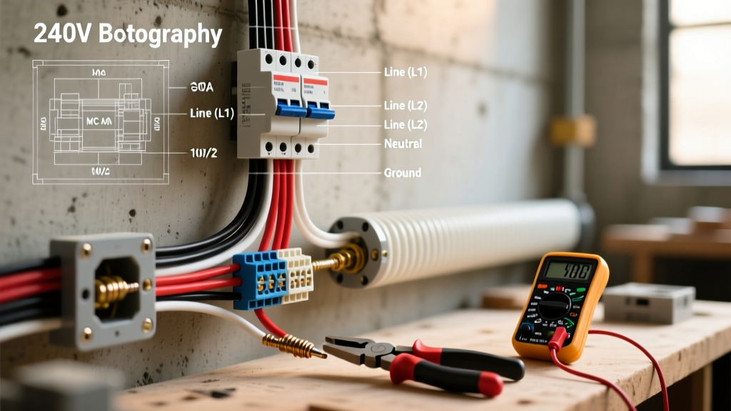
Turn off the main breaker to de-energize the panel. Install the 2-pole breaker into an available double-slot space, ensuring it clips firmly onto both bus bars. Connect the bare copper ground wire to the panel's ground bus bar, and the white neutral wire to the neutral bus bar. Critical Code Note: In a standard 240V baseboard circuit, the white neutral wire in the 12/2 NM-B cable is not used for the heater circuit itself. It must be capped off with a wire nut at both the panel and the heater junction box. Re-identify the white wire with black electrical tape at both ends to signify it is being used as a second hot leg, per NEC Article 200.7(C).
Step 2: Rough-In and Cable Routing
Run the NM-B cable from the panel to the thermostat location, and then from the thermostat to the baseboard heater's internal junction box. Secure the cable with cable staples within 8 inches of every electrical box and at intervals no greater than 4.5 feet, complying with NEC 300.11. Maintain a minimum clearance of 12 inches above the heater to prevent thermal damage to the wire insulation.
Step 3: Line-Voltage Thermostat Termination
Mount the line-voltage thermostat to the wall box. You will have two sets of 12/2 wires entering the box: the "Line" (from the panel) and the "Load" (to the heater).
- Connect the bare ground wires from both cables together and pigtail them to the thermostat's green grounding screw.
- Connect the black "Line" wire to the thermostat's L1 terminal.
- Connect the white "Line" wire (taped black) to the thermostat's L2 terminal.
- Connect the black "Load" wire to the thermostat's T1 terminal.
- Connect the white "Load" wire (taped black) to the thermostat's T2 terminal.
- Cap the unused neutral wires together with a red wire nut.
Step 4: Heater Element Connection
At the baseboard heater's junction box, connect the black and white (taped black) load wires to the two flexible lead wires extending from the heating element. Because this is a 240V alternating current circuit, polarity does not matter; either hot wire can connect to either element lead. Secure the connections with Wago 221 lever nuts or twist-on wire nuts, ensuring no bare copper is exposed outside the connector.
Single-Pole vs. Double-Pole Thermostat Wiring
Choosing the right thermostat impacts both safety and user experience. The UL Electrical Safety guidelines heavily favor double-pole configurations for line-voltage heating.
| Feature | Single-Pole Thermostat | Double-Pole Thermostat |
|---|---|---|
| Wiring Terminals | 2 (Breaks one hot leg) | 4 (Breaks both hot legs) |
| "Off" Setting | No true "Off" (only low temp limit) | True "Off" position available |
| Safety Profile | Moderate (120V still present at element) | High (0V at element when off) |
| Cost (Approx.) | $25 - $35 | $40 - $65 |
Expert Recommendation: Always install a double-pole thermostat (like the Cadet T410A). If a single-pole thermostat fails in the "closed" position, or if maintenance is required, the heating element remains energized with 120V to ground, presenting a severe shock hazard.
Advanced Troubleshooting and Edge Cases
Edge Case 1: Daisy-Chaining Multiple Heaters
You can wire multiple baseboard heaters in parallel on a single 240V circuit, provided the total continuous wattage does not exceed 80% of the breaker's capacity. For example, on a 20A breaker (3840W max continuous), you could daisy-chain two 1500W heaters (3000W total). To do this, run a 12/2 cable from the first heater's junction box to the second. Connect black-to-black, white-to-white, and ground-to-ground. Never wire them in series, as this will halve the voltage to each element, resulting in 25% of the intended heat output.
Edge Case 2: 120V Heater on a 240V Circuit
If you accidentally wire a 120V-rated baseboard heater to a 240V supply, Ohm's Law dictates that the current will double, and the power dissipation will quadruple. The heating element will glow red hot and burn out within seconds, posing an immediate fire hazard. Always verify the manufacturer's data plate on the heater casing before terminating wires.
NEC Code Compliance and Safety Mandates
As we navigate the 2026 NEC cycle, local jurisdictions are increasingly strict about clearances and arc-fault protection. While standard baseboard heaters do not universally require AFCI (Arc-Fault Circuit Interrupter) protection unless installed in specific dwelling areas like bedrooms (depending on local amendments), GFCI protection is generally not required for hardwired baseboard heaters unless they are located within 6 feet of a water source, which is highly discouraged by design.
Furthermore, the NFPA 70 National Electrical Code mandates strict spatial clearances. Combustible materials, including heavy drapes or furniture, must be kept at least 12 inches away from the front and top of the heater. Ensure the thermostat is mounted on the wall at standard switch height (48 inches to the center of the box) and is not placed directly above the heater where rising thermal drafts will cause short-cycling and premature mechanical failure of the bimetallic strip.
By following this exact wiring diagram and respecting the continuous load mathematics, your 240V electric baseboard heating system will deliver decades of safe, silent, and efficient zone heating.