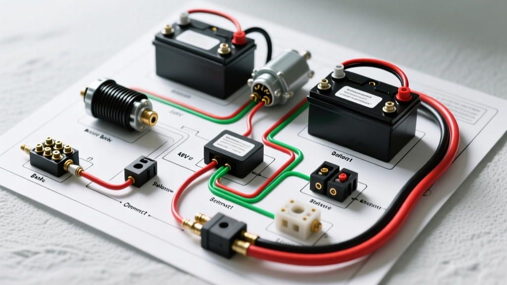

Introduction to 48V Golf Cart Battery and Motor Wiring
As electric vehicle technology has matured, the 48V architecture has become the undisputed standard for modern electric golf carts. Whether you are restoring a vintage Club Car DS or upgrading a 2026 Yamaha Drive2, understanding the wiring diagram for golf cart batteries and their integration with the motor controller is critical. A flawed high-current connection doesn't just cause voltage drop; it generates enough thermal runaway to melt terminal lugs and destroy expensive silicon in the motor controller. This guide breaks down the exact wiring sequence, wire gauge requirements, and torque specifications needed to safely wire a 48V battery bank to a modern AC motor controller.
Why 48V is the 2026 Standard
While 36V systems were common in the early 2000s, 48V systems deliver 33% more power without increasing current draw, allowing for smaller, lighter wiring harnesses. In 2026, most OEM carts utilize 48V to support high-torque AC induction motors and advanced telemetry systems, making a precise wiring schematic mandatory for any DIY repair or lithium upgrade.
Core Components in the Wiring Diagram
Before running any cables, verify you have the correct high-amperage components. Modern setups have moved away from brushed DC series motors to high-efficiency AC motors. A standard 2026 performance wiring diagram includes:
- Battery Bank: Six 8V deep-cycle lead-acid batteries (e.g., Trojan T-875) or a single 48V LiFePO4 drop-in module (e.g., RELiON RB48V60P).
- Motor Controller: Alltrax XCT-48550-MOD or Curtis 1268-5403 (rated for 550A peak).
- Main Solenoid (Contactor): 48V 400A continuous duty HD solenoid with pre-charge terminals.
- Motor: HPEVS AC-35 or KDS 10kW AC Induction Motor (3-phase).
- Throttle Box: 0-5V Hall-effect sensor (replacing legacy inductive pots).
Step-by-Step: Wiring the Battery Bank (Series Configuration)
The foundation of your wiring diagram for golf cart batteries is the bank configuration. To achieve 48V, batteries must be wired in series. This adds the voltage of each battery while keeping the amp-hour (Ah) capacity constant.
| Battery Type | Quantity | Individual Voltage | Total Pack Voltage | Wiring Method |
|---|---|---|---|---|
| 8V Deep Cycle (Lead-Acid) | 6 | 8V | 48V | Series (Positive to Negative) |
| 12V Deep Cycle (Lead-Acid) | 4 | 12V | 48V | Series (Positive to Negative) |
| 6V Deep Cycle (e.g., T-105) | 8 | 6V | 48V | Series (Positive to Negative) |
| 48V LiFePO4 (Lithium) | 1 | 51.2V Nominal | 51.2V | Single Module (Parallel for capacity) |
Crucial Wiring Rule: Your main positive cable must connect to the positive terminal of Battery #1, and your main negative cable must connect to the negative terminal of the last battery in the series chain. Wiring both main cables to the same battery will cause severe imbalance and premature cell death.
High-Current Circuit: Solenoid and Controller Wiring
The high-current circuit carries the full amperage load from the batteries to the motor controller. Use only 2 AWG or 1/0 AWG Class K fine-stranded silicone wire for these runs to handle the 300A+ peak loads without excessive voltage drop.
- Main Positive to Solenoid: Run a 2 AWG cable from the main positive battery bank terminal to the large input stud on the HD solenoid.
- Solenoid to Controller B+: Run a 2 AWG cable from the large output stud on the solenoid to the B+ (Battery Positive) terminal on the motor controller.
- Main Negative to Controller B-: Run a 2 AWG cable directly from the main negative battery bank terminal to the B- (Battery Negative) terminal on the controller. Never route the main negative through the solenoid or a disconnect switch.
The Pre-Charge Circuit (Mandatory for AC Controllers)
Modern motor controllers contain large internal capacitors. If the main solenoid closes without pre-charging these capacitors, the instantaneous inrush current will weld the solenoid contacts or blow the controller's internal MOSFETs. Your wiring diagram must include a pre-charge resistor (typically 470-ohm, 50W) wired in parallel across the solenoid's large terminals, or utilize a controller with a dedicated pre-charge driver pin.
Motor Connections: 3-Phase AC vs. Legacy DC
If you are wiring a legacy DC series motor, the diagram will show two heavy cables (A1 and A2) connecting the controller to the motor. However, 90% of 2026 setups use 3-phase AC motors. For an AC motor like the HPEVS AC-35, the controller outputs three phases:
- Phase U (M1): 2 AWG cable to Motor Terminal U
- Phase V (M2): 2 AWG cable to Motor Terminal V
- Phase W (M3): 2 AWG cable to Motor Terminal W
Note: Swapping any two of the three phase wires will reverse the motor's direction of rotation. This is how forward/reverse is electronically managed in modern carts, eliminating the need for heavy mechanical reversing contactors.
Wire Gauge and Terminal Torque Specifications
Loose terminals are the number one cause of golf cart electrical fires. According to Trojan Battery's official maintenance guidelines, under-torqued terminals lead to arcing and thermal expansion. Always use a calibrated inch-pound torque wrench.
| Connection Point | Stud Size | Recommended Wire Gauge | Target Torque (in-lbs) |
|---|---|---|---|
| Battery Terminals (Lead-Acid) | 5/16" or 3/8" | 2 AWG or 1/0 AWG | 90 - 120 in-lbs |
| Controller B+ / B- Busbars | 5/16" | 2 AWG | 110 - 130 in-lbs |
| Solenoid Large Studs | 3/8" | 2 AWG | 120 - 140 in-lbs |
| AC Motor Phase Terminals | M8 or 5/16" | 2 AWG | 100 - 120 in-lbs |
| Low-Current Signal Pins | 18-14 AWG | 18 AWG | Hand-tight / Ferrule crimp |
Common Wiring Failures and Troubleshooting
When a cart fails to move or the controller throws an error code, the issue is rarely the motor itself. Use a digital multimeter to perform a voltage drop test under load.
Expert Diagnostic Tip: Place your multimeter probes across any single connection (e.g., from the battery post to the cable lug). Have a helper press the throttle. If you measure a voltage drop greater than 0.15V across that single joint, the crimp is failing or the terminal is corroded. A healthy high-current connection should show less than 0.05V drop under a 200A load.
Failure Mode: The 'Click-No-Go' Solenoid Issue
If the solenoid clicks but the cart doesn't move, the low-current activation circuit is working, but the high-current path is failing. Check the micro-switch on the accelerator box, ensure the controller is receiving the 0-5V throttle signal, and verify that the main 400A fuse (located within 18 inches of the main positive battery terminal) has not blown.
Upgrading to LiFePO4: Diagram Adjustments
Transitioning from lead-acid to lithium (like the RELiON RB48V60P) requires specific modifications to your wiring diagram. Lithium batteries feature an internal Battery Management System (BMS) that will disconnect the pack if it detects a short circuit or over-current event.
- Remove the OBC: Bypass or remove the factory On-Board Computer charging relay, as lithium requires a specific CC/CV charging profile.
- Charge Interlock: Wire the BMS 'Charge Enable' signal to the charger receptacle to prevent the charger from pushing 58.4V into a BMS that has tripped into protection mode.
- DC-DC Converter: Ensure your 48V-to-12V step-down converter is rated for the peak amperage of your accessories (lights, stereo), as lithium BMS units will shut down instantly if the 12V draw exceeds the converter's input rating.
Summary and Safety Protocols
Executing a flawless wiring diagram for golf cart batteries requires strict adherence to AWG sizing, proper series topology, and precise torque specifications. Always disconnect the main negative battery cable first, and reconnect it last. Cover all exposed high-current lugs with adhesive-lined heat shrink tubing to prevent accidental short circuits against the cart's chassis. By following these 2026 industry standards, you ensure maximum torque delivery, extended battery life, and absolute electrical safety on the course.