
The Challenge of Vintage Honda Wiring with Color Vision Deficiency
Restoring a classic Honda CT90 Trail 90 is a rite of passage for vintage motorcycle enthusiasts. However, navigating the factory wiring harness presents a unique hurdle for technicians and DIYers with Color Vision Deficiency (CVD). According to the National Eye Institute, roughly 1 in 12 men experience some form of color blindness, most commonly deuteranopia (red-green color blindness).
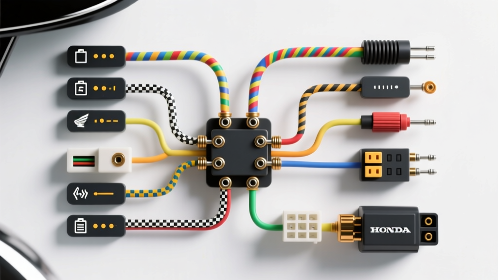
For a colorblind installer, the CT90's original 1960s and 1970s wiring palette is a nightmare. The factory harness relies heavily on red (switched power), green (ground/sensors), yellow (AC lighting), and light green with red stripes. After 50 years of heat cycling, oil exposure, and UV damage, these wires fade into indistinguishable shades of brown, gray, and muddy yellow. Relying on a standard color-coded CT90 wiring diagram is not just frustrating; it is a primary cause of short circuits and blown 6-volt rectifiers. This installation planning guide shifts the paradigm from color-reliance to topology-based circuit mapping, ensuring a safe, reliable harness installation.
Phase 1: Shifting to Topology-Based Planning
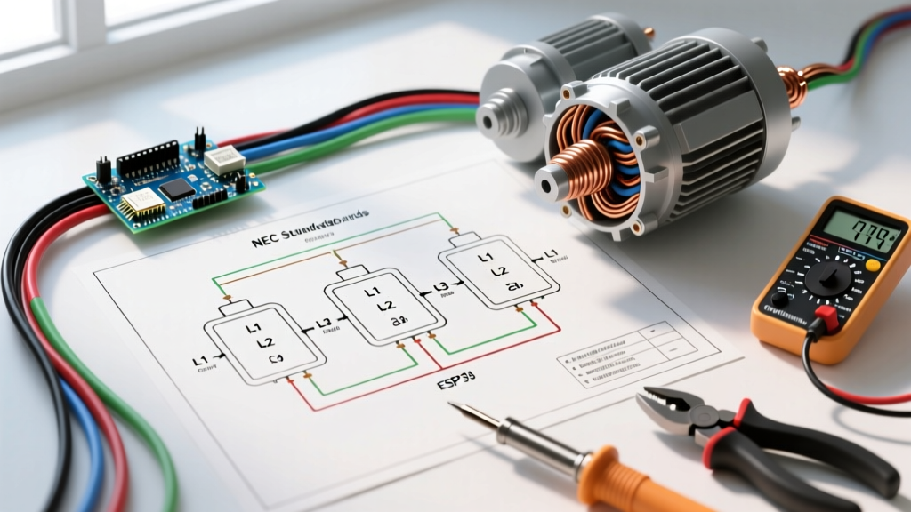
When color is removed from the equation, you must plan your installation based on circuit topology and physical routing. The Honda CT90 utilizes a mixed AC/DC 6-volt system. The stator generates alternating current (AC) directly for the headlight, while a selenium rectifier converts a separate AC tap into direct current (DC) for the battery, taillight, and horn.
Instead of asking, "Which wire is yellow?", the colorblind installer must ask, "Which pin on the stator connector corresponds to the headlight switch input?" By mapping the harness via connector pinouts and continuity testing, you bypass the need for visual color identification entirely.
Phase 2: Essential Diagnostic and Labeling Arsenal
To execute a color-agnostic installation, you need specific tools that provide audible, tactile, or alphanumeric feedback. Budget approximately $250 to $350 for this specialized toolkit in 2026.
- Digital Multimeter with Audible Continuity: The Klein Tools MM400 (approx. $55) features a loud, distinct continuity beep. As noted in Fluke's electrical testing guides, an audible cue allows you to trace wires from the engine cases to the headlight bucket without staring at the screen or the wire insulation.
- Tone Generator and Probe: The Fox and Hound Tone Generator (approx. $45) is invaluable for tracing a specific wire through the dense, taped-up main harness bundle without stripping back insulation.
- Alphanumeric Wire Labeler: The Brady BMP21-PLUS (approx. $160) with nylon cloth labels creates permanent, wrap-around text labels. This replaces color-coding with text-coding (e.g., printing "HL-AC" for Headlight Alternating Current).
- Tactile Marker Tape: 3M ScotchCode Wire Marker Tape (approx. $25 per roll) allows you to wrap numbered or lettered vinyl tape around wire ends before soldering or crimping.
Phase 3: Decoding the CT90 by Circuit Function
Below is a function-based mapping table for the standard 1969-1979 Honda CT90 6V harness. This matrix ignores wire color completely, focusing instead on the source, destination, and electrical characteristics. Use your multimeter's continuity setting to verify these paths during your bench-test phase before wrapping the harness.
| Circuit Function | Source / Origin | Destination / Load | Current Type | Verification Method (No Color) |
|---|---|---|---|---|
| Headlight High/Low | Stator Output (Yellow wire terminal) | Handlebar Dimmer Switch | AC (Alternating) | Continuity from stator pin to switch; reads infinite resistance to frame ground. |
| Taillight / Brake Light | Battery Positive (via Main Switch) | Rear Fender Lamp | DC (Direct) | Continuity from battery fuse block to rear lamp; checks for 6V DC with key ON. |
| Ignition / Points | Magneto Points Plate | Ignition Coil (Primary) | Pulsed DC | Continuity from points plate to coil; must show open circuit when points are manually opened. |
| Charging System | Stator Charging Tap | Selenium Rectifier | AC to DC | Continuity from stator to rectifier AC input; verify rectifier DC output reads ~7.2V at 3,000 RPM. |
| Horn Circuit | Battery Positive (via Switch) | 6V Horn Unit | DC (Direct) | Continuity from handlebar horn button to horn bracket; horn bracket grounds to frame. |
Phase 4: Implementing a Tactile and Alphanumeric Labeling Standard
Once continuity is verified, you must label the wires so that future troubleshooting does not require re-testing. For colorblind technicians, the SAE J1128 standard for automotive wire identification can be adapted using text and tactile markers.
Pro-Tip for Harness Wrapping: Before applying non-adhesive harness tape (like Tesa 51036 PET cloth tape), apply a 2-inch piece of heat-shrink tubing over the wire ends. Slide the tubing back, wrap your Brady text label around the wire, and then slide the clear or black heat-shrink over the label. This protects the text from fuel spills and finger oils, ensuring your alphanumeric system survives decades of use.
Recommended Alphanumeric Legend for CT90
- IGN-1: Ignition points to coil primary.
- HL-AC: Stator to headlight dimmer (AC).
- TL-DC: Main switch to taillight (DC).
- BRK-SW: Brake light switch input.
- REC-AC: Stator to rectifier input.
- BAT-POS: Rectifier output to battery positive.
Edge Case: Planning a 6V to 12V Conversion
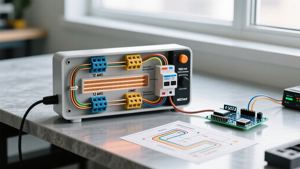
Many CT90 owners upgrade to a 12-volt system to support modern LED lighting and USB charging. If you are planning a 12V conversion, wire gauge becomes a physical identifier you can use to your advantage, as outlined in SAE automotive wiring standards.
In a 6V system, voltage drop is a massive issue, requiring thicker wires (typically 14 AWG or 16 AWG) for the headlight circuit to prevent dimming. When converting to 12V, the current (Amps) is halved for the same wattage bulb. You can safely downsize the headlight circuit to 18 AWG. Information Gain: Use the physical thickness of the wire as a tactile identifier. Use 14 AWG wire exclusively for the main battery feeds and starter solenoid (if equipped), and use 18 AWG for all switched lighting and sensor circuits. By feeling the wire thickness inside the harness bundle, you can instantly differentiate high-amperage feeds from low-amperage signal wires without looking at them.
FAQ: CT90 Wiring for the Colorblind Technician
How do I identify the ground wires without relying on the green color code?
On the CT90, the frame and engine block act as the primary ground return path. The only dedicated "ground" wires in the harness are those connecting the battery negative terminal to the frame, and the stator/points plate ground to the engine cases. Verify these by testing for zero resistance (continuity) between the wire end and a clean, bare metal spot on the engine block.
What if the previous owner butchered the harness and replaced wires with random colors?
This is where the tone generator becomes your best friend. Clip the tone generator to a known component (like the horn button terminal), and use the inductive probe to trace the exact path of that wire through the harness bundle. Mark both ends immediately with your alphanumeric labeler before moving to the next circuit.
Are there any specific connectors I should replace during this planning phase?
Yes. The original Honda bullet connectors and the 4-pin stator connector are notorious for corrosion, which increases resistance and mimics a broken wire. Replace all engine-side connections with modern, sealed Deutsch DT series or Sumitomo waterproof connectors. This not only improves reliability but provides a secondary identification method: you can use different connector cavity counts (e.g., a 2-pin for ignition, a 4-pin for stator) to physically prevent miswiring.
Final Installation Checklist
Before applying the final layer of harness tape and mounting the tank, run through this color-agnostic checklist:
- [ ] All alphanumeric labels are sealed under heat-shrink tubing.
- [ ] Continuity verified from battery positive to main fuse block.
- [ ] Stator AC headlight tap verified isolated from frame ground (no short to ground).
- [ ] Rectifier DC output verified at 7.2V (6V system) or 14.2V (12V system) at 3,000 RPM using a multimeter, not a test light.
- [ ] Wire gauge physically verified by touch for high-draw vs. low-draw circuits.
By abandoning the flawed reliance on faded, 50-year-old color codes and embracing topology, continuity, and alphanumeric labeling, colorblind technicians can wire a Honda CT90 with greater accuracy and reliability than those relying solely on the factory diagram.