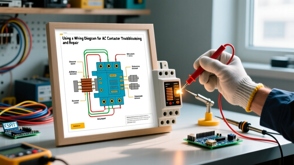

The Critical Role of the Wiring Diagram for AC Contactor Diagnostics
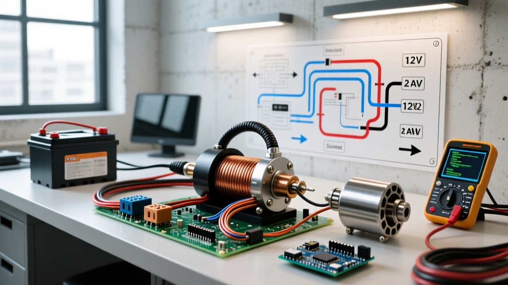
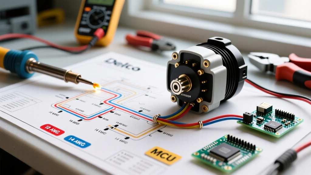
In residential and light commercial HVAC systems, the AC contactor acts as the heavy-duty gatekeeper between your thermostat’s low-voltage commands and the high-voltage demands of the compressor and condenser fan motor. When an air conditioning system fails to engage, hums loudly, or trips the breaker, technicians and advanced DIYers must rely on a wiring diagram for AC contactor circuits to isolate the fault. Guessing without a schematic often leads to misdiagnosed control boards or unnecessarily replaced compressors.
According to the U.S. Department of Energy, regular maintenance and precise electrical diagnostics are essential for maintaining HVAC efficiency and preventing catastrophic component failure. This guide provides a deep-dive, expert-level framework for using contactor wiring diagrams to troubleshoot 240VAC split-phase systems, complete with multimeter test points, failure matrices, and 2026 replacement market data.
⚠️ CRITICAL SAFETY WARNING: Before removing any access panels or testing terminals, disconnect all power at the main service panel and the outdoor disconnect switch. Always adhere to OSHA electrical safety standards and utilize Lockout/Tagout (LOTO) procedures. Verify zero voltage with a CAT III or CAT IV rated multimeter before touching any terminals.Decoding the Schematic: Key Symbols and Terminals
To effectively troubleshoot, you must first translate the symbols on your unit’s wiring schematic into physical test points on the contactor. Most residential systems use a Definite Purpose (DP) 2-pole contactor.
- Line Side (L1 & L2): The incoming 240VAC power from the outdoor disconnect. These are typically the top terminals.
- Load Side (T1 & T2): The outgoing 240VAC power feeding the compressor and condenser fan. These are typically the bottom terminals.
- Coil Terminals (A1 & A2): The 24VAC control circuit originating from the contactor relay on the indoor air handler or furnace control board. Some diagrams label these simply as 'C' (Common) and 'Y' (Compressor call).
- Auxiliary Contacts (NO/NC): Normally Open or Normally Closed side contacts used for crankcase heaters or safety interlocks, though less common on basic residential DP contactors.
Step-by-Step Troubleshooting Using the Diagram
When the thermostat calls for cooling, the control board sends 24VAC to the contactor coil. The electromagnetic field pulls the plastic plunger down, bridging the L and T terminals. Here is how to trace this sequence using your wiring diagram.
Step 1: Verify the Control Circuit (24VAC)
Set your multimeter to AC Voltage (VAC). With the thermostat calling for cooling and power restored to the control board (but high voltage safely managed), probe the A1 and A2 coil terminals.
- Expected Reading: 22VAC to 28VAC.
- Troubleshooting Insight: If you read 0V, the fault is upstream. Trace the diagram back to the control board, low-pressure switch, or high-pressure switch. If you read 24V but the contactor doesn't pull in, the coil is likely burnt open (proceed to Step 3).
Step 2: Verify Line and Load Power (240VAC)
Set your multimeter to measure up to 600VAC. Probe L1 to L2.
- Expected Reading: 230VAC to 250VAC.
- Troubleshooting Insight: If L1-L2 reads 0V or 120V, check the outdoor disconnect fuses and the main breaker. Next, probe T1 to T2. If L1-L2 has 240V, the coil is energized (24V present), but T1-T2 reads 0V, the internal contacts are severely pitted, carbonized, or mechanically jammed.
Step 3: Coil Resistance Testing (Power OFF)
Shut off all power. Set the multimeter to Ohms (Ω). Disconnect the 24V wires from A1 and A2, and probe the coil terminals directly.
- Expected Reading: 10Ω to 25Ω (varies by manufacturer and VA rating).
- Troubleshooting Insight: A reading of 'OL' (Open Loop) means the internal copper winding is broken. A reading near 0Ω indicates a shorted coil. In either case, the contactor must be replaced.
Diagnostic Matrix: Symptoms vs. Multimeter Readings
Use this quick-reference matrix to cross-verify your field measurements against common failure modes.
| System Symptom | Coil Voltage (A1-A2) | Line Voltage (L1-L2) | Load Voltage (T1-T2) | Probable Diagnosis |
|---|---|---|---|---|
| Compressor won't start, fan runs | 24VAC | 240VAC | 120VAC (T1-L2) | One pole of the contactor is welded open or pitted; lost leg on load side. |
| Contactor hums/chatters loudly | 16VAC - 19VAC | 240VAC | Fluctuating | Voltage drop on control circuit; loose wire nut; debris in magnetic gap. |
| Unit runs when thermostat is OFF | 0VAC | 240VAC | 240VAC | Contacts are mechanically welded shut due to high LRA (Locked Rotor Amps) arcing. |
| Nothing engages, coil smells burnt | 24VAC | 240VAC | 0VAC | Coil winding shorted/open; plunger failed to pull in; thermal overload on coil. |
Advanced Edge Cases and Failure Modes
Experienced technicians know that a wiring diagram for an AC contactor only tells half the story. Physical environmental factors and interacting components heavily influence contactor lifespan.
1. Contact Welding from Weak Run Capacitors
If the dual run capacitor (e.g., a 45/5 MFD) degrades, the compressor struggles to start, drawing massive Locked Rotor Amps (LRA) for a prolonged period. This extreme current arcs across the contactor points as they close, melting the silver-alloy coating and welding the contacts together. Always test the run capacitor with a multimeter's capacitance setting before blaming a welded contactor.
2. Contactor Chattering and the 'Hold-In' Voltage Threshold
A 24VAC coil requires roughly 80% of its nominal voltage (approx. 19.2V) to initially pull in the plunger, but only about 60% (approx. 14.4V) to hold it in. If your control wire run exceeds 75 feet using 18 AWG thermostat wire, voltage drop can cause the coil to chatter. The wiring diagram will help you identify if a control relay or a heavier gauge (16 AWG) wire is needed to compensate for the distance.
3. Ant and Insect Intrusion
Fire ants and earwigs are notoriously attracted to the magnetic field and warmth of energized coils. They crawl into the plunger gap, creating a physical barrier that prevents the contacts from fully seating. This results in high resistance, localized melting of the plastic housing, and eventual failure.
Sizing and Replacement Guidelines (2026 Market Data)
When replacing a faulty unit, sizing must comply with NFPA 70 (National Electrical Code) Article 440, which governs motor-compressor circuits. You must match the Full Load Amps (FLA) and Locked Rotor Amps (LRA) printed on the compressor nameplate to the contactor's rating.
Expert Tip: Never downsize a contactor. If the original schematic calls for a 40A contactor, do not install a 30A unit, even if the compressor's FLA is only 18A. The contactor must be rated to handle the brutal LRA spike during startup without degrading.
In the 2026 HVAC parts market, standard 2-pole Definite Purpose (DP) contactors remain highly affordable. Popular, reliable models include:
- Eaton C25DNF330 (30A, 24V): Typically priced between $16 and $22. Excellent for standard 1.5 to 2.5-ton residential units.
- Siemens 3TF41 / DP30X2 (30A, 24V): Priced around $18 to $25. Known for robust silver-cadmium oxide contacts that resist welding.
- Carrier / Bryant OEM Replacements (40A): Often rebranded Eaton units, but carrying an OEM markup, pricing them between $35 and $55.
Note: Always replace the plastic protective cover over the coil terminals. Leaving it off exposes the 24V connections to rain and condensation, leading to short circuits.
Frequently Asked Questions
Can I use a 3-pole contactor in place of a 2-pole unit?
Yes, but with caveats. A 3-pole contactor (often used in commercial 3-phase systems) can be wired for single-phase residential use by simply routing the high-voltage wires through L1/T1 and L2/T2, leaving L3/T3 empty. However, ensure the coil voltage is 24VAC, as many 3-pole industrial contactors utilize 120VAC or 208VAC coils. Check the wiring diagram for the specific coil rating before applying control voltage.
Why does my wiring diagram show a crankcase heater wired through the contactor?
Many schematics route the crankcase heater through the Normally Closed (NC) auxiliary contacts of the contactor. When the contactor is OFF (winter or between cycles), the NC contacts close, powering the heater to keep refrigerant from migrating and pooling as liquid in the compressor oil. When the contactor pulls IN to run the AC, the NC contacts open, cutting power to the heater. If you replace the contactor and forget to wire the auxiliary block, you risk severe compressor liquid slugging on the next startup.
Is it safe to manually push the contactor plunger with a screwdriver to test the compressor?
While veteran technicians sometimes use an insulated screwdriver to manually depress the plunger to verify compressor function, this is highly discouraged for DIYers. If the run capacitor is weak or the compressor is mechanically seized, manually closing the contacts will draw massive LRA, creating a dangerous arc flash that can melt the screwdriver tip and cause severe burns. Always rely on multimeter diagnostics and capacitor testing first.