
When a ceiling fan loses its speed settings, hums without spinning, or fails to turn on entirely, the culprit is often the internal speed control switch or the wall control unit. Searching for a wiring diagram for 4 wire ceiling fan switch configurations usually leads DIYers to two distinct electrical scenarios: replacing the internal 4-terminal pull-chain switch, or installing a 4-wire smart wall control. This comprehensive appliance wiring tutorial breaks down both configurations with exact terminal mappings, capacitor interactions, and critical safety standards for 2026.
Understanding the 4-Wire Designation
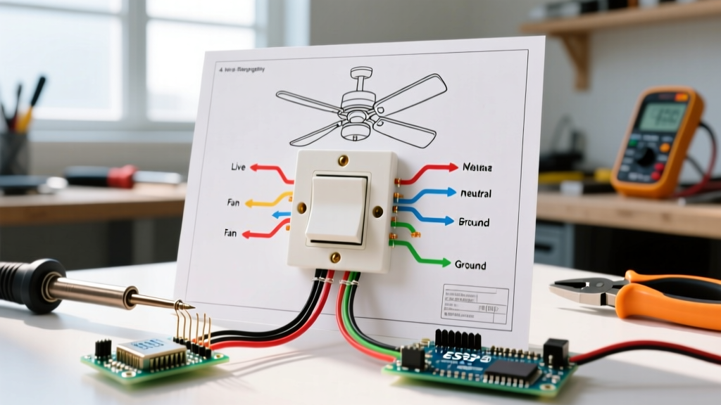
In ceiling fan terminology, the phrase 4-wire can refer to the internal micro-switch (Terminals: L, 1, 2, 3) or a wall-mounted dual-control switch (Wires: Line, Neutral, Fan Load, Light Load). Misidentifying which system you are working on is the leading cause of blown capacitors, melted wire nuts, and tripped AFCI breakers. Before cutting any wires, determine if you are repairing the fan's internal mechanism or upgrading the wall switch.
Scenario A: The Internal 4-Wire Pull Chain Switch
The internal switch (commonly found in Hunter, Harbor Breeze, and Hampton Bay models) does not regulate voltage directly. Instead, it acts as a rotary router, directing 120V AC line voltage to specific taps on the fan's CBB61 run capacitor. If you wire the switch without referencing the capacitor's microfarad taps, the fan will hum violently, run backward, or operate at a single speed regardless of the pull chain position.
Tools and Replacement Parts
- Replacement Switch: Litomaster ZE-268s6 or Hunter 27183 (Typically $7 to $12).
- Capacitor (if needed): CBB61 5uF+5uF+5uF 250VAC (Typically $6 to $9).
- Testers: Fluke 117 True RMS Multimeter and Klein NCVT-1 Non-Contact Voltage Tester.
- Wire Strippers: Klein 11055 (Specifically calibrated for 18 AWG stranded wire).
Terminal Mapping and Capacitor Interaction
| Switch Terminal | Wire Color (Typical) | Destination / Function | Capacitor Tap (Example) |
|---|---|---|---|
| L (Line) | Black (Hot) | Power In from Inductor/Light Kit | N/A (Direct 120V) |
| 1 | Red or White | Speed 1 (Usually High or Low) | Tap 1 (e.g., 5uF) |
| 2 | Blue or Yellow | Speed 2 (Medium) | Tap 2 (e.g., 5uF + 5uF) |
| 3 | White or Black | Speed 3 (Off or Bypass) | Tap 3 (Direct Bypass) |
Expert Insight: Never trust wire colors blindly. Aftermarket replacement switches often swap the red, blue, and white wire assignments compared to OEM Hunter switches. Always trace the physical wires from the switch to the CBB61 capacitor terminals to verify the exact sequence before making connections.
Step-by-Step Replacement Procedure
- Kill the Power: Turn off the 15A or 20A branch circuit breaker at the main panel. Verify zero voltage at the fan canopy using a multimeter set to AC Voltage.
- Drop the Canopy: Remove the canopy screws to access the wiring harness. Locate the small rectangular switch housing near the motor stator.
- Document the OEM Wiring: Before pulling a single wire, take a macro photo of the existing switch and the capacitor. Note exactly which color wire goes to L, 1, 2, and 3.
- Extract the Old Switch: Use a small flathead screwdriver to depress the retaining clip on the switch housing and push the switch out from the inside of the metal cup.
- Terminate the New Switch: Strip exactly 3/16 inch of insulation from the 18 AWG stranded wires. Crimp on insulated spade connectors if the new switch requires them, or insert bare wire into the push-in terminals until fully seated.
- Test the Sequence: Before reassembling the canopy, restore power temporarily and pull the chain through all four positions. If the fan runs backward or only has one speed, you have a capacitor tap mismatch that requires re-routing.
Advanced Diagnostics: Testing the CBB61 Capacitor
Many DIYers replace the 4-wire switch only to find the fan still hums and refuses to spin. In 80% of these cases, the switch was fine, but the CBB61 capacitor failed. To test it, turn off the power, disconnect the capacitor, and safely discharge it using a 20k ohm 5W resistor across the terminals. Set your multimeter to the capacitance setting (denoted by the µF symbol). A healthy 5uF tap should read between 4.75uF and 5.25uF. If it reads significantly lower, or shows an open circuit (OL), the capacitor is dead and must be replaced with an identical microfarad rating.
Scenario B: The 4-Wire Smart Wall Control
If your project involves upgrading a standard toggle to a smart fan and light control (like the Lutron Caseta PD-FSQN or Leviton DW4SF, priced between $45 and $65 in 2026), you are dealing with a 4-wire wall box setup. These switches require a constant neutral wire to power their internal Wi-Fi or Zigbee radios, which older homes often lack.
Wall Box Wire Identification
- Line (Hot): Black wire from the breaker panel carrying 120V.
- Neutral: White wire (or gray). Critical: Pre-1980s homes frequently lack a neutral in the switch box, requiring a neutral-less smart switch like the Lutron PD-5S-DV.
- Load 1 (Fan): Typically Red or Black, running up the 14/3 or 12/3 Romex to the fan motor.
- Load 2 (Light): Typically Blue or Black, running to the fan's integrated light kit.
Troubleshooting Common Failure Modes
| Symptom | Root Cause | Actionable Fix |
|---|---|---|
| Fan hums loudly but blades do not spin | Failed CBB61 capacitor (not the switch) | Replace capacitor with identical uF rating. Do not use a higher voltage rating as a substitute. |
| Fan only runs on High, regardless of pull chain | Terminal L and Terminal 1 are swapped | Re-route the Line hot wire to L and the first capacitor tap to 1. |
| Smart wall switch flickers LED light kit | Incompatible LED driver or missing bypass resistor | Install a Lutron LUT-MLC bypass resistor across the light load and neutral at the canopy. |
| Breaker trips immediately upon pulling chain | Short circuit in switch housing or pinched wire | Inspect for pinched 18 AWG wires against the sharp metal edge of the switch cup. |
Frequently Asked Questions
Can I use a 3-wire switch on a 4-wire fan?
No. A 3-wire switch only offers Off, Low, and High (or Medium). It lacks the internal contact to route power to the third capacitor tap. Attempting to force a 3-wire switch into a 4-wire harness will result in the loss of a speed setting and potential motor overheating due to improper phase shifting.
What if my wall box does not have a neutral wire?
If your wall box only contains a Line, a Ground, and two Load wires, you cannot install a standard 4-wire smart switch. You must either pull a new 14/3 or 12/3 cable from the ceiling canopy to the switch box to introduce a neutral, or purchase a specialized no-neutral smart switch that utilizes a bypass resistor at the fan canopy to complete the circuit.
Safety and NEC Code Compliance
According to NFPA 70 (National Electrical Code) Article 410, ceiling fans and their associated lighting assemblies must be securely supported independently of the outlet box if they exceed 35 pounds. Furthermore, when working on the wall switch, the U.S. Department of Energy recommends ensuring that the wall control is rated for the specific amperage of the fan motor. Most standard fan motors draw between 0.5A and 1.2A, but heavy-duty models can exceed 2.0A. Ensure your smart switch is explicitly rated for inductive motor loads, not just resistive lighting loads, to prevent internal relay welding and fire hazards.
Mastering the wiring diagram for 4 wire ceiling fan switch configurations requires patience and a methodical approach to tracing capacitor taps. By verifying wire sequences rather than relying on generic color codes, you ensure a safe, long-lasting repair that maintains the fan's torque, efficiency, and quiet operation.