
Architecting the Modern 60V Electric Scooter
Building or upgrading a high-performance electric scooter requires a meticulous approach to electrical architecture. The 60v electric scooter wiring diagram is the foundational blueprint that dictates not only the performance of your ride but also its safety and longevity. In the current landscape of DIY electric mobility, a '60V' system typically refers to a 16-series (16S) Lithium-Ion NMC battery pack, which operates at a nominal 59.2V and peaks at 67.2V when fully charged. Alternatively, some legacy or heavy-duty builds use five 12V Lead-Acid batteries in series, though lithium setups have largely dominated the 2026 market due to their superior energy density and discharge rates.
This installation planning guide breaks down the exact component selection, wire gauge requirements, and routing strategies necessary to execute a flawless 60V scooter build. Whether you are wiring a Dualtron clone, a custom Sur-Ron conversion, or a standalone commuter deck, understanding the interplay between the Battery Management System (BMS), the Field Oriented Control (FOC) motor controller, and the peripheral accessories is critical.
Core Component Selection & Bill of Materials
Before cutting a single wire, you must finalize your component list. Mismatched components are the leading cause of thermal runaway and controller burnout. Below is a benchmarked Bill of Materials (BOM) for a high-reliability 60V build, reflecting current market pricing and availability.
| Component | Recommended Specification | Est. Cost | Primary Wire Gauge |
|---|---|---|---|
| Battery Pack | 16S Li-ion NMC (59.2V Nominal), 20Ah - 30Ah, 5P config | $450 - $650 | 8 AWG Silicone |
| Smart BMS | JBD-SP16S020 (60A Continuous, Bluetooth, UART) | $85 - $110 | 8 AWG Silicone |
| Motor Controller | Votol EM-100 or Sabvoton SVMC72100 (FOC, 72V max rating) | $170 - $210 | 8 AWG (Power), 10 AWG (Phase) |
| DC-DC Converter | 36V-72V Input to 12V Output, 10A Max (Waterproof IP67) | $35 - $50 | 14 AWG (Input), 16 AWG (Output) |
| Main Disconnect | XT90-S (Anti-Spark) Connector with 150A Fuse | $18 - $25 | 8 AWG |
Deconstructing the 60V Electric Scooter Wiring Diagram
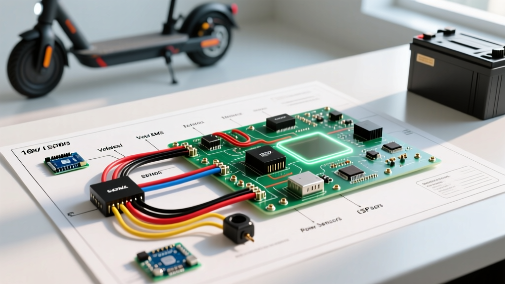
A complete wiring diagram for a 60V scooter is divided into three distinct subsystems: High-Voltage Power Routing, Motor Phase & Sensor Wiring, and Low-Voltage Accessories. Treating these as isolated circuits prevents signal interference and catastrophic short circuits.
1. High-Voltage Power Routing (Battery, BMS, and Controller)
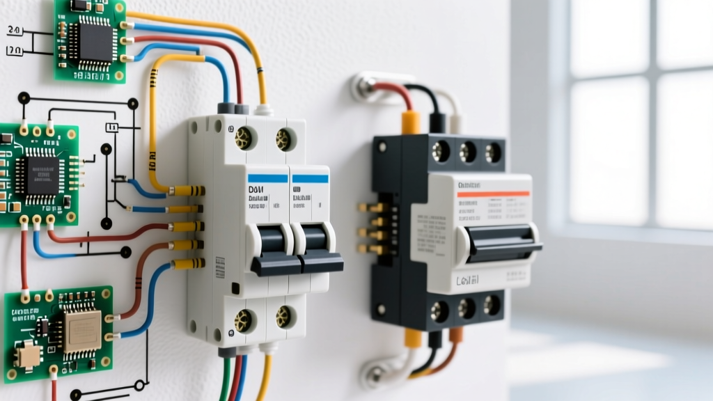
The main power loop carries the bulk of the current, often peaking at 40A to 60A during hard acceleration. The wiring sequence must follow a strict path to ensure the BMS can properly monitor and protect the cells.
- Battery Negative to BMS B-: The main negative trunk from the battery pack solders directly to the B- pad on the JBD Smart BMS.
- BMS P- to Controller Negative: The discharge negative (P-) on the BMS routes to the main negative terminal of the Votol EM-100 controller. Never bypass the BMS on the negative line.
- Battery Positive to Controller Positive: The main positive trunk routes through an XT90-S anti-spark connector and an inline 150A ANL fuse before terminating at the controller's positive terminal.
- BMS Charge Port (C-): A separate, smaller gauge wire (12 AWG) routes from the BMS C- pad to the charge port negative, allowing the BMS to balance cells during charging without carrying the massive discharge current of the motor.
2. Phase Wires & Hall Sensor Calibration
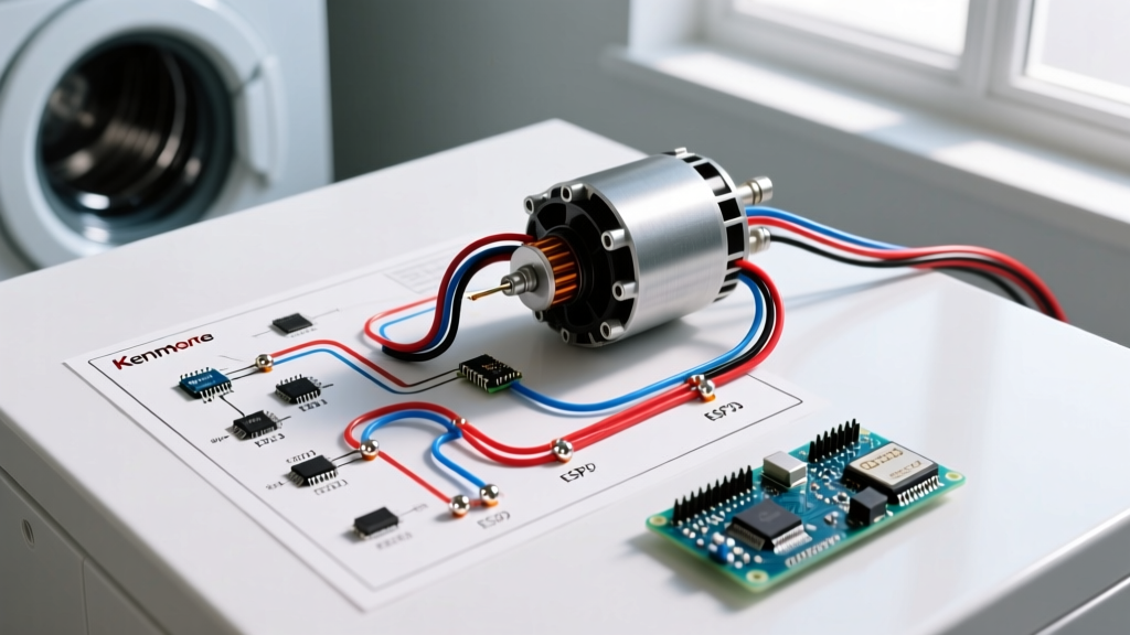
Brushless DC (BLDC) hub motors rely on three thick phase wires (A, B, C) and a delicate 5-wire Hall sensor harness. Incorrect phase wiring will result in violent motor stuttering, immediate overheating, and potential controller MOSFET failure.
For the Votol EM-100, use 10 AWG high-strand silicone wire for the phase connections. Because the deck space is confined, route the phase wires away from the low-voltage signal wires to prevent Electromagnetic Interference (EMI). The Hall sensor harness uses 22 AWG wire. Ensure your motor uses a 120-degree Hall sensor phasing, which is the standard for modern FOC controllers. If your motor uses 60-degree phasing, you must reconfigure the physical Hall sensors inside the motor stator or use the Votol PC software to apply a software offset, though hardware correction is always preferred for signal stability.
3. Low-Voltage Accessories & DC-DC Step-Down
Scooter headlights, taillights, horns, and turn signals operate on 12V. Tapping 60V directly into a 12V bulb will instantly destroy it. You must wire a waterproof DC-DC step-down converter.
- Connect the DC-DC high-voltage input wires (Red/Black) directly to the controller's switched power lines, not directly to the battery. This ensures the lights only turn on when the scooter is keyed on.
- Route the 12V output to a secondary fuse block mounted near the handlebars.
- Use 18 AWG wire for the 12V lighting runs to minimize voltage drop over the long distance from the deck to the handlebars.
Wire Gauge Sizing & Routing Best Practices
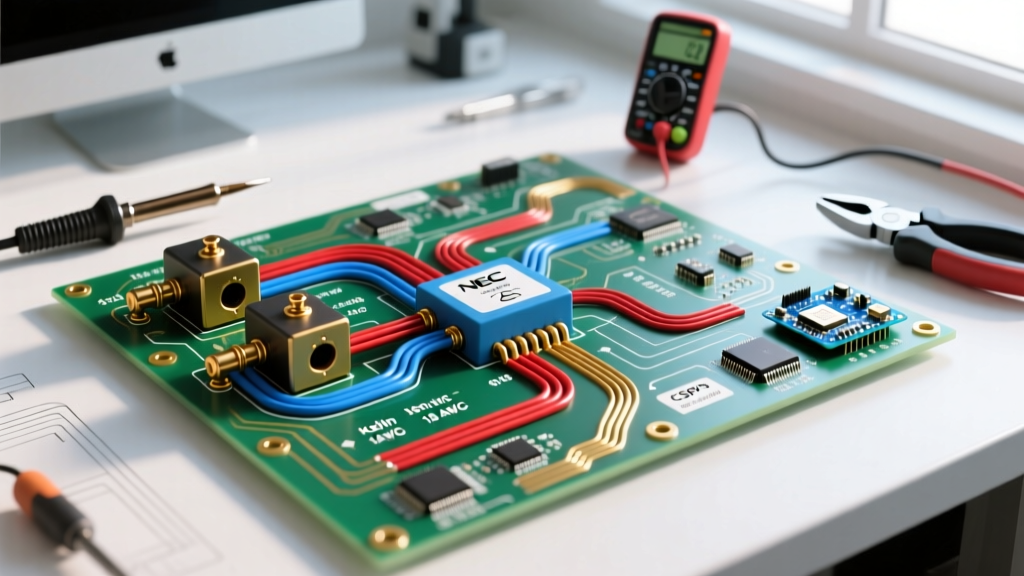
Selecting the correct wire gauge is non-negotiable. According to data published by the Engineering Toolbox, wire ampacity drops significantly when wires are bundled together in a confined space like a scooter deck, due to the inability to dissipate heat. Always size your wires for the peak current, not the continuous current.
Expert Routing Tip: When crimping 8 AWG silicone wire for XT90 or MR30 connectors, do not use standard stamped automotive crimpers. Use a dedicated hex-die crimper with a 10mm² die. A poor crimp creates high resistance, which will melt the connector housing under a 50A load within minutes of riding.
Furthermore, always use heat-shrink tubing with an inner layer of marine-grade adhesive sealant over all soldered and crimped joints. The vibration of a scooter deck will eventually fatigue bare solder joints, leading to intermittent power loss or short circuits against the aluminum deck.
Common Wiring Failure Modes & Troubleshooting
Even with a perfect 60v electric scooter wiring diagram, physical installation errors occur. Here are the most common failure modes encountered during the initial power-up phase:
- Throttle Signal Mismatch: If the scooter turns on but the motor spins to 100% immediately without touching the throttle, your 5V reference and Signal wires on the throttle plug are swapped. Most Hall-effect throttles use a 3-pin JST connector: Red (5V), Black (Ground), Green/White (Signal). Verify with a multimeter before plugging it into the controller.
- BMS Bluetooth Disconnects Under Load: If your JBD Smart BMS app disconnects the moment you accelerate, the BMS UART wires are picking up EMI from the phase wires. Route the BMS communication wires on the opposite side of the battery pack from the motor phase wires.
- DC-DC Converter Overheating: If your 12V lights flicker or the DC-DC converter shuts down, you are likely exceeding its amperage rating. LED headlights draw minimal current, but if you add a high-decibel air horn or heated grips, a standard 5A DC-DC will fail. Upgrade to a 10A or 15A unit.
Step-by-Step Installation Sequence
To prevent accidental shorting and component damage, follow this exact power-up sequence when finalizing your 60V build:
- Bench Test the BMS: Before installing the battery in the deck, connect the BMS sense leads to the battery pack. Use a multimeter to verify the voltage on the B- and P- pads. Wake up the BMS by applying charge voltage or connecting the Bluetooth module to confirm all 16 cell groups are reading within 0.030V of each other.
- Mount Controller and DC-DC: Apply thermal paste or thermal pads between the Votol controller and the aluminum scooter deck. The deck acts as a massive heatsink. Secure with M4 stainless steel hardware.
- Wire Low-Voltage First: Connect all Hall sensors, throttle, brake cut-offs, and the DC-DC converter to the controller. Do not connect high-voltage power yet.
- Connect Phase Wires: Secure the motor phase wires. Ensure they are physically separated from the Hall sensor harness.
- Final Power Connection: Plug in the XT90-S anti-spark connector. You should hear a faint 'click' as the pre-charge resistor equalizes the controller capacitors. If you see a large spark, stop immediately and check for a dead short.
- Software Configuration: Connect the Votol controller to your laptop via the RS485-to-USB cable. Set the battery parameters (16S, 67.2V max, 52V cutoff) and calibrate the throttle voltage range (usually 0.8V to 3.6V).
Battery Chemistry and Longevity Considerations
When planning your 60V wiring, the battery chemistry dictates your charging and cutoff parameters. As detailed in the comprehensive guides on Battery University, series configurations multiply the voltage while maintaining the capacity of a single cell string. For a 16S NMC pack, setting your controller's low-voltage cutoff to 51.2V (3.2V per cell) is critical to prevent irreversible anode degradation. Furthermore, resources from Grin Technologies (Ebikes.ca) emphasize that voltage sag under heavy load can trick a poorly configured BMS into triggering a premature cutoff. Always size your battery's continuous discharge rate (C-rating) to be at least 20% higher than your controller's maximum programmed battery current limit.
By adhering strictly to this installation planning guide and respecting the physical realities of high-current DC wiring, your 60V electric scooter will deliver reliable, high-torque performance for thousands of miles.