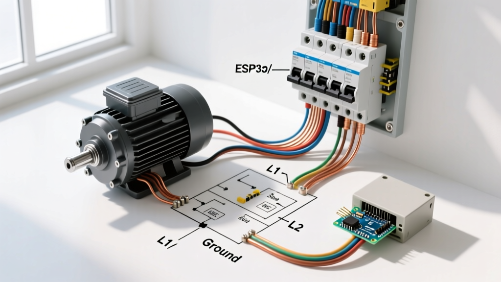

The Inductive Challenge: Why Motors Break Standard Rules
Wiring a standard resistive load, like a baseboard heater or an incandescent lighting circuit, is a straightforward exercise in matching wire ampacity to breaker size. However, routing power from your main electrical wiring circuit breaker panel to an electric motor introduces a complex set of variables governed by inductive physics. When an AC motor starts, it experiences Locked Rotor Amperage (LRA)—an inrush current that can be six to eight times higher than its normal running current. As noted by Fluke's electrical engineering resources, this massive transient spike lasts for a few seconds but is more than enough to trip a standard thermal-magnetic circuit breaker if the circuit is not sized according to specialized motor rules.
This tutorial provides a master-class approach to wiring single-phase and three-phase motors (ranging from 3HP to 10HP) directly from an electrical wiring circuit breaker panel. We will cover the National Electrical Code (NEC) Article 430 requirements, precise breaker selection, wire sizing methodologies, and the physical installation steps required for a safe, code-compliant termination.
NEC Article 430: The Sizing Matrix for Your Panel
The NFPA 70: National Electrical Code (NEC) dedicates Article 430 entirely to motors, motor circuits, and controllers. The most common mistake DIYers and junior electricians make is sizing the breaker based on the wire's ampacity (e.g., putting a 30A breaker on 10 AWG wire). For motor circuits, the NEC separates overload protection (which protects the motor from burning out) from short-circuit and ground-fault (SC-GF) protection (which protects the wire from catching fire during a dead short).
Step 1: Determine Full Load Amps (FLA)
Never use the horsepower rating alone to size wires. You must use the FLA printed on the motor nameplate. If the nameplate is missing, you must refer to NEC Table 430.250 (Three-Phase) or Table 430.248 (Single-Phase). For example, a 5HP, 240V, 3-phase motor has a standard FLA of 15.2 Amps.
Step 2: Size the Branch Circuit Conductors
NEC 430.22 requires conductors supplying a single continuous-duty motor to be sized at 125% of the motor's FLA.
Calculation: 15.2A × 1.25 = 19 Amps.
Using the 75°C column of NEC Table 310.16 (standard for modern panel terminations), 12 AWG THHN copper wire is rated for 25 Amps, which safely covers the 19A requirement. However, for mechanical durability and voltage drop mitigation over long conduit runs, 10 AWG THHN is highly recommended as the minimum baseline for any 5HP motor circuit.
Step 3: Size the SC-GF Breaker
NEC 430.52 dictates the maximum rating for the breaker in your electrical wiring circuit breaker panel. For a standard inverse-time thermal-magnetic breaker, the maximum size is 250% of the motor FLA.
Calculation: 15.2A × 2.50 = 38 Amps.
According to NEC 240.6 (standard breaker sizes), you must round down to the nearest standard size, which is 35 Amps. Therefore, you will install a 35A 3-pole breaker on 10 AWG wire. This is a deliberate exception to standard wiring rules, allowing the breaker to hold the massive LRA inrush spike without nuisance tripping, while the motor's internal thermal overloads protect the motor itself from sustained overcurrent.
Motor Sizing Cheat Sheet (240V Systems)
The following table provides baseline parameters for common shop and HVAC motors wired from a 240V panel. Always verify against the specific motor nameplate.
| Motor HP | Phase | Approx. FLA | Min. Wire Size (THHN 75°C) | Max Inverse-Time Breaker |
|---|---|---|---|---|
| 3 HP | 1-Phase | 17.0A | 10 AWG | 40A (2-Pole) |
| 5 HP | 1-Phase | 28.0A | 8 AWG | 70A (2-Pole) |
| 5 HP | 3-Phase | 15.2A | 12 AWG (10 AWG Rec.) | 35A (3-Pole) |
| 7.5 HP | 3-Phase | 22.0A | 10 AWG | 50A (3-Pole) |
| 10 HP | 3-Phase | 28.0A | 8 AWG | 70A (3-Pole) |
Selecting the Breaker: HACR vs. MCP
When reaching into your inventory to populate the electrical wiring circuit breaker panel, the type of breaker matters immensely for inductive loads.
- HACR Rated Breakers: If you are wiring a single-phase HVAC compressor or condenser unit, NEC 440 requires the breaker to be marked "HACR" (Heating, Air Conditioning, and Refrigeration). These breakers (like the Square D QO series or Eaton BR series) have specialized magnetic trip calibrations designed to ignore the severe, repetitive inrush currents of compressor motors.
- Motor Circuit Protectors (MCP): For industrial 3-phase panels, standard thermal-magnetic breakers are often replaced by MCPs (magnetic-only breakers). An MCP provides instantaneous short-circuit protection but relies on a separate, downstream NEMA-rated motor starter with integrated overload relays to handle thermal protection. Brands like Schneider Electric (TeSys series) and Siemens (MMP series) dominate this space.
Step-by-Step: Routing from the Panel to the Disconnect
Safety and precision are non-negotiable when working inside a live or recently de-energized panel. Follow this exact sequence when pulling a new motor circuit.
1. Panel Preparation and Torque Specifications
Shut off the main service disconnect. Verify the absence of voltage on the bus bars using a CAT III or CAT IV non-contact voltage tester and a multimeter. Modern NEC codes (110.14(D)) mandate the use of a calibrated torque screwdriver for all panel terminations. For a standard Square D QO or Homeline panel, the lug torque specification is typically 35 in-lbs for 14-8 AWG wires. Overtightening can strip the aluminum bus threads; undertightening causes high-resistance connections that will arc and melt under the heavy starting loads of a motor.
2. Conduit Routing and Pulling THHN
Motors require physical protection. Route EMT (Electrical Metallic Tubing) or Liquidtight Flexible Metal Conduit (LFMC) from the panel knockout to the motor's local disconnect switch. When pulling THHN/THWN-2 conductors, apply NEC Chapter 9 conduit fill rules. For three current-carrying conductors plus a ground in 1/2-inch EMT, you have plenty of room, but always use a high-quality wire pulling lubricant (like Ideal 747) to prevent micro-tears in the wire insulation, which can lead to ground faults when the motor vibrates during operation.
3. Landing the Connections
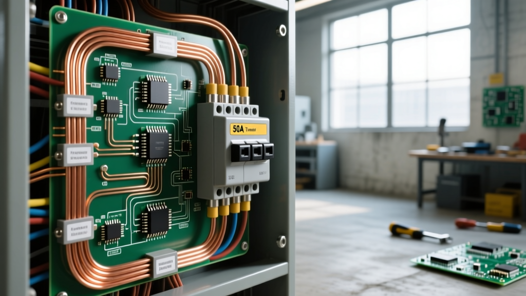
Snap the appropriately sized breaker (e.g., a Siemens Q235 35A 2-pole) onto the bus bar stab. Ensure it is fully seated. Strip exactly 3/4 inch of insulation from the THHN conductors. Land the hot conductors on the breaker lugs and torque to spec. Land the equipment grounding conductor (EGC) on the panel's dedicated ground bar. Never land a ground wire on the neutral bar in a subpanel, and never bond the neutral and ground in a subpanel.
Expert Warning: When wiring the local disconnect switch outside the panel, ensure the disconnect is rated for the specific horsepower. A standard 30A/60A residential AC disconnect box is usually rated for a specific HP limit (often up to 3HP or 5HP). If you are wiring a 7.5HP motor, you must use a heavy-duty NEMA-rated disconnect or a manual motor starter to safely handle the inductive arc generated when the disconnect is pulled under load.
Voltage Drop: The Hidden Motor Killer
If your electrical wiring circuit breaker panel is located more than 100 feet from the motor, standard NEC ampacity tables are no longer sufficient. Motors are highly sensitive to voltage drop; a voltage drop of just 10% results in a severe reduction in starting torque (torque decreases with the square of the voltage) and causes the motor to draw excess amperage to compensate, leading to overheating and premature winding failure.
NEC Informational Note 210.19(A)(1) recommends a maximum 3% voltage drop for branch circuits. For a 5HP, 240V, 3-phase motor located 150 feet from the panel, 10 AWG wire will yield a 4.2% drop. You must upsize to 8 AWG THHN copper to bring the drop down to a safe 2.6%, ensuring the motor starts reliably even when the utility grid is experiencing low-voltage brownouts.
Common Failure Modes and Troubleshooting
- Nuisance Tripping on Startup: The breaker trips the second the contactor engages. Cause: The breaker is sized too small (based on wire ampacity rather than NEC 430.52 motor rules), or an incorrect breaker curve (like a standard lighting breaker instead of HACR) was used. Fix: Verify FLA, calculate 250%, and upsize to the next standard breaker size.
- Motor Overheats and Internal Overload Trips: The panel breaker holds fine, but the motor shuts off after 3 minutes of runtime. Cause: Voltage drop due to undersized wires over a long distance, or mechanical binding on the driven load causing high running amps. Fix: Measure voltage at the motor terminals while under load. If it reads below 216V (on a 240V system), upsize the conductors.
- Contactor Chatter and Welding: Cause: Sizing the control circuit incorrectly or voltage sag pulling the contactor coil out of its holding range. Ensure the control circuit transformer is adequately sized (minimum 100VA for most industrial contactors).
Final Commissioning Checklist
Before energizing the electrical wiring circuit breaker panel, perform a final mechanical and electrical audit. Verify all wire strands are fully inserted into the lugs with no copper exposed outside the termination point. Confirm the equipment ground path is continuous using a multimeter. Finally, energize the panel, engage the motor, and use a clamp-on true-RMS ammeter to measure the running current on all phases. The measured amperage should be at or slightly below the nameplate FLA. If the phases are unbalanced by more than 5%, immediately shut down the system and investigate the panel terminations for high-resistance connections.