
The Intersection of Dash Electronics and Circuit Protection
When enthusiasts and professional fabricators tackle a custom build, EV swap, or resto-mod, the wiring diagram for instrument cluster integration is often reduced to matching colored pins on a connector. However, from a Panel & Breaker Guide perspective, the true reliability of a digital or analog dash lies in how it is fed, fused, and grounded by the vehicle's central power distribution module (PDM) or fuse block. A poorly designed panel feed will result in boot-looping TFT screens, corrupted CAN bus data, and premature component failure.
As of 2026, high-resolution digital dashes like the Holley Digital Dash (551-100) or Dakota Digital VHX series dominate the aftermarket, retailing between $650 and $1,200. These units are essentially ruggedized computers. They require clean, stable DC voltage. In this guide, we dissect the wiring diagram for instrument cluster power feeds, focusing strictly on breaker selection, fuse panel topology, and wire gauge calculations to ensure your dash survives the harsh electrical environment of a modern vehicle.
Core Power Feeds: Interpreting the Wiring Diagram for Instrument Cluster Protection
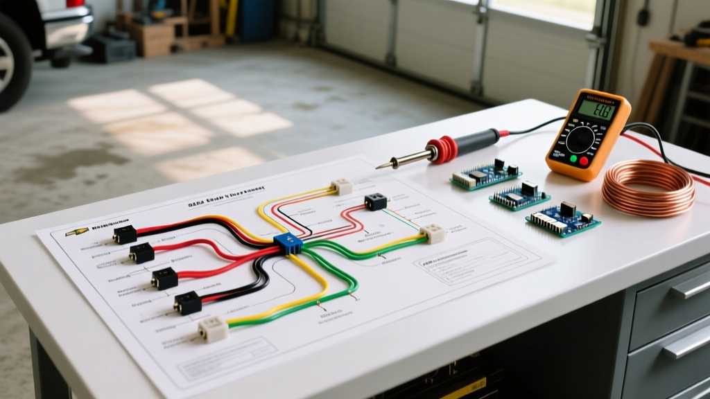
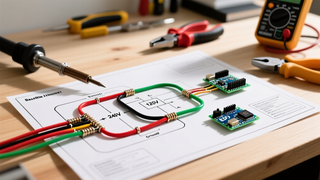
Every comprehensive wiring diagram for instrument cluster setups will define at least two distinct 12V power feeds, plus a ground. Understanding the electrical behavior of each circuit dictates how you route them through your fuse panel.
Constant 12V (Keep-Alive Memory)
This circuit maintains the cluster's internal memory (odometer, trip data, user settings) when the ignition is off. The current draw is typically micro-amps. However, because this wire is tied directly to the battery through the main panel, it is highly susceptible to voltage spikes from the alternator or inductive loads (like fuel pumps or cooling fans) shutting down. Panel Rule: This feed should be protected by a dedicated 3A or 5A ATO blade fuse located as close to the main battery distribution stud as possible.
Switched 12V (Ignition / Wake-Up)
This is the high-current feed that wakes up the cluster's processors and illuminates the screen. Digital clusters experience a massive inrush current upon startup as capacitors charge and the TFT backlight inverter powers up. A cluster rated for 2.5 Amps continuous draw may spike to 6 Amps for 50 milliseconds during ignition. If your fuse panel utilizes standard thermal circuit breakers instead of blade fuses, this inrush spike can nuisance-trip the breaker, preventing the dash from ever turning on.
Expert Panel Tip: Never use a thermal auto-reset circuit breaker for the direct switched ignition feed of a digital instrument cluster. The bi-metallic strip inside the breaker reacts too slowly to distinguish between an inrush spike and a dead short, and the breaker's internal inductance can generate a voltage kickback that damages the cluster's internal voltage regulators. Always use a time-delay ATO/ATM blade fuse paired with a TVS (Transient Voltage Suppression) diode at the fuse block.
Fuse Panel Sizing and Breaker Selection for Digital Dashes
When designing or selecting a fuse panel for a custom chassis, you must match the protection device to the specific cluster's power envelope. Below is a reference matrix based on 2026 specifications for popular aftermarket and OEM-swap clusters.
| Cluster Model | Continuous Draw | Inrush Spike | Recommended Fuse | Min Wire Gauge | Max Run Length (12V) |
|---|---|---|---|---|---|
| Holley Digital Dash (551-100) | 2.5A | 5.5A | 7.5A ATO Blade | 16 AWG | 12 Feet |
| Dakota Digital VHX-69C-CAM | 1.8A (CCB Box) | 4.0A | 5A ATM Blade | 18 AWG | 10 Feet |
| AutoMeter EV Dash (2650) | 3.2A | 7.0A | 10A ATO Blade | 14 AWG | 15 Feet |
| GM GMT800 OEM Cluster (LS Swap) | 1.2A | 2.5A | 3A ATO Blade | 18 AWG | 14 Feet |
Wire Gauge and Voltage Drop: The Math Behind the Diagram
A wiring diagram for instrument cluster integration is useless if the physical wire gauge cannot support the run length. Digital dashes are notoriously sensitive to voltage drop. If the voltage at the cluster's connector falls below 11.2V during cranking, the processor will brown-out, resulting in a continuous boot loop or corrupted EEPROM memory.
According to SAE International J1128 standards for low-tension primary automotive cable, standard copper wire has specific resistance metrics. For example, 18 AWG copper wire has a resistance of approximately 6.385 milliohms per foot.
- The Calculation: If you run 10 feet of 18 AWG wire from the fuse panel to the dash, the total circuit length (power + ground return) is 20 feet.
- The Drop: 20 ft × 0.006385 Ω = 0.1277 Ω total resistance.
- At 3 Amps: 3A × 0.1277 Ω = 0.38V drop.
While a 0.38V drop seems negligible, if your alternator is only outputting 13.8V, and the starter solenoid causes a momentary system sag to 11.5V during cranking, that 0.38V drop pushes the cluster below its operational threshold. Always upsize your wire by one gauge (e.g., use 16 AWG instead of 18 AWG) for any firewall-to-dash run exceeding 6 feet.
Grounding Topology: The Hidden Half of the Wiring Diagram
The most common failure point in custom instrument cluster wiring is the ground return path. The wiring diagram will usually show a simple chassis ground symbol, but in practice, relying on sheet metal screws into a painted firewall is a recipe for erratic gauge behavior and CAN bus dropouts.
Star Grounding vs. Daisy Chaining
When configuring your fuse panel and grounding block, implement a star grounding topology. Run a dedicated, heavy-gauge ground wire (minimum 10 AWG) from the negative battery terminal or main engine block to a centralized, cleaned copper busbar behind the dashboard. From this busbar, run individual, equal-gauge ground wires to the instrument cluster, the ECU, and the radio.
Never daisy-chain the cluster ground with high-current accessories like HVAC blower motors or halogen headlights. The return current from those accessories will seek the path of least resistance, which can inadvertently route through the cluster's internal ground traces, instantly vaporizing the delicate PCB pathways.
Troubleshooting Dead Clusters: A Panel-to-Dash Diagnostic Flow
When a newly wired cluster fails to illuminate, do not immediately assume the unit is defective. Use this systematic, panel-outward diagnostic flow to isolate the fault.
- Verify Panel Input Voltage: Using a digital multimeter (DMM), measure the voltage at the main feed stud of the fuse block. It should read within 0.2V of the battery's resting voltage (approx. 12.6V). If lower, your main panel feed wire is undersized or corroded.
- Check the Fuse Voltage Drop: With the ignition ON, place your DMM probes on the test points on top of the ATO blade fuse. A healthy fuse will show less than 0.1V drop. A reading of 0.5V or higher indicates a corroded fuse terminal or a cheap, off-brand fuse panel with poor internal busbar stampings.
- Measure at the Connector (Back-Probe):**gt; Back-probe the constant and switched 12V pins at the back of the cluster connector while it is plugged in. This measures the voltage under actual load. If you have 12.6V at the panel but only 10.8V at the connector, you have a high-resistance fault in the wire run or a crimp terminal failure.
- Validate the Ground Return: Switch your DMM to continuity mode (with power OFF). Measure from the cluster ground pin to the engine block. Resistance must be less than 0.5 Ohms. If higher, strip the paint off the chassis grounding point and apply dielectric grease to prevent future oxidation.
Real-World Integration: LS Swap GMT800 Cluster to Aftermarket Fuse Block
One of the most popular budget swaps in 2026 remains the GMT800 (1999-2006 GM truck) instrument cluster, utilized for its built-in driver information center and CAN-bus compatibility with GM LS/LT ECUs. When integrating this OEM cluster into an aftermarket fuse panel like a Painless Performance 21-circuit block, specific wiring diagram adaptations are required.
The GMT800 cluster requires a Class 2 serial data line (pin 2 of the green connector) to communicate with the PCM. This data line must be routed as a twisted pair to prevent electromagnetic interference (EMI) from the alternator. Furthermore, the panel must supply a clean, unswitched 12V to pin 11 (Battery) and a switched 12V to pin 13 (Ignition 3). Many DIYers mistakenly wire the cluster illumination to a standard 12V headlight switch feed, but the GMT800 requires a Pulse Width Modulated (PWM) ground signal from the Body Control Module (BCM) for dimming. If you are running a standalone harness without a BCM, you must wire a manual 100-ohm potentiometer to the dimming circuit to prevent the dash from defaulting to maximum brightness, which accelerates LED backlight degradation.
Conclusion and Component Selection
Reading a wiring diagram for instrument cluster setups is only the first step; executing the power distribution is where builds succeed or fail. By prioritizing time-delay blade fuses over thermal breakers, calculating voltage drop based on SAE J1128 wire metrics, and enforcing strict star-grounding topologies, you ensure your digital or analog dash operates flawlessly. For high-quality circuit protection components, always source from established manufacturers like Littelfuse Automotive Blade Fuses rather than relying on generic bulk-bin assortments, ensuring your $1,000 digital dash is protected by a $0.50 fuse that actually meets its amperage rating.
Whether you are wiring a Holley EFI system or a standalone AutoMeter EV dash, treat the fuse panel as the heart of the vehicle's nervous system. Clean power in equals reliable data out.