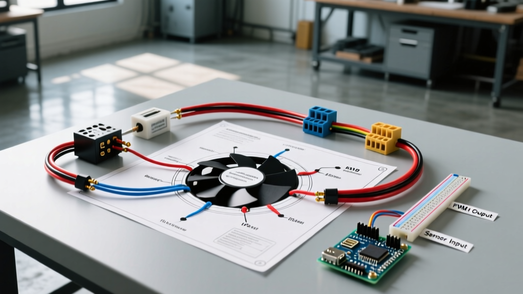

Introduction: The Evolution of 12V Cooling Fan Circuits
When upgrading a classic muscle car, optimizing a track vehicle, or converting a daily driver to electric cooling, understanding a 12 volt electric fan wiring diagram is critical. Mechanical clutch fans rob horsepower and offer inconsistent airflow at low RPMs. Modern electric setups—especially the brushless PWM (Pulse Width Modulation) models dominating the 2026 aftermarket—demand precise electrical management. A poorly wired 35-amp fan can melt harnesses, trigger severe voltage drops, or fail silently, leading to catastrophic engine overheating.
This guide deconstructs the standard 12V fan relay circuit, explains the physics of DC motor inrush currents, and provides actionable wiring matrices for both traditional brushed motors and modern brushless controllers.
⚠️ Critical Safety Warning: Never wire a high-amperage cooling fan directly through a dashboard toggle switch or a basic thermal probe. The inrush current of a DC motor can be 3 to 5 times its running amperage. This spike will instantly weld the contacts of a standard 15A switch or melt a low-gauge thermal sensor.Anatomy of a Standard 12 Volt Electric Fan Wiring Diagram
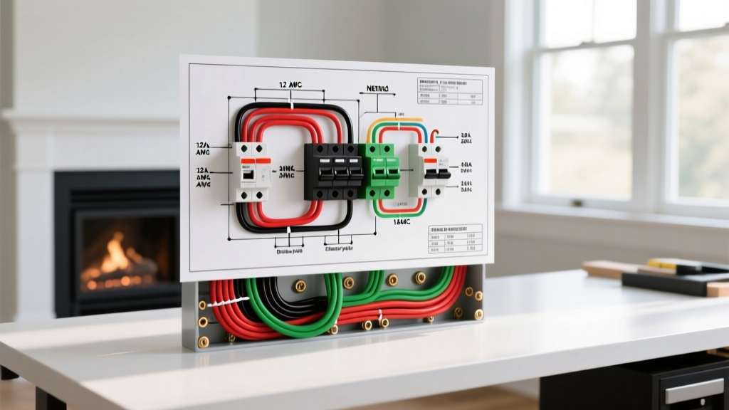
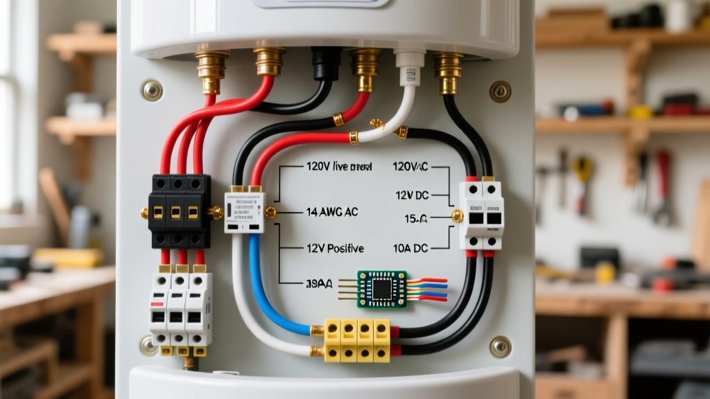
A robust automotive cooling circuit is divided into two distinct paths: the Control Circuit (low amperage) and the Load Circuit (high amperage). The bridge between these two circuits is the relay.
The Core Components
- The Relay (Bosch-Style ISO Mini): The workhorse of the circuit. Standard automotive relays use a 4-pin or 5-pin layout. For cooling fans, we use the 4-pin SPST (Single Pole, Single Throw) configuration. Terminals 85 and 86 form the electromagnetic coil (Control), while terminals 30 and 87 form the high-current switch (Load).
- The Thermal Switch / Thermostat: Devices like the Derale 16749 billet thermostat probe monitor coolant temperatures. They act as the 'brain', completing the ground path for the relay coil when the threshold (e.g., 185°F) is reached.
- The Overcurrent Protection (Fuse): Placed on the main power feed before the relay. For high-draw fans, MAXI or ANL fuses are required over standard ATO blade fuses.
- The Flyback Diode: Often overlooked in amateur diagrams. When the relay coil de-energizes, it sends a high-voltage spike backward through the control circuit. A 1N4007 diode placed across pins 85 and 86 (stripe facing power) protects sensitive ECU triggers or delicate thermal switches from arc damage.
Traditional Brushed vs. 2026 Brushless PWM Fan Wiring
The automotive aftermarket has shifted heavily toward brushless cooling fans (such as the latest iterations from Spal and Mishimoto). Understanding the difference in wiring is vital.
Traditional Brushed DC Motors
These require the full relay setup described above. The motor draws massive current directly through the relay contacts (Pin 30 to Pin 87). Because of the carbon brushes, these motors generate electrical noise (EMI) and suffer from high inrush startup currents.
Modern Brushless PWM Fans
Brushless fans feature an integrated electronic speed controller (ESC). In many 2026 setups, the ESC handles the heavy amperage switching internally.
Expert Insight: Some advanced PWM fans only require a 12V trigger signal (under 2 amps) from a thermostat or ECU to turn on, eliminating the need for an external 40A mechanical relay entirely. Always consult the specific manufacturer's ESC pinout before adding redundant external relays.
Wire Gauge Selection Chart for 12V DC Fan Motors
Selecting the correct American Wire Gauge (AWG) is based on the fan's continuous amperage draw and the total length of the wire run (positive + negative). Undersized wire causes voltage drop, reducing fan RPM and CFM output while generating dangerous heat. Referencing data aligned with the Engineering Toolbox AWG standards, use the matrix below:
| Fan Type / CFM | Continuous Amps | Peak Inrush Amps | Wire Gauge (Under 10 ft) | Wire Gauge (10-15 ft) | Recommended Fuse (Slow-Blow) |
|---|---|---|---|---|---|
| 10" - 12" Standard (800-1200 CFM) | 8A - 12A | ~35A | 14 AWG | 12 AWG | 20A MAXI |
| 16" High-Performance (2000-2500 CFM) | 18A - 22A | ~65A | 12 AWG | 10 AWG | 30A MAXI |
| 16" Extreme Duty / Dual Puller (3000+ CFM) | 28A - 35A | ~90A+ | 10 AWG | 8 AWG | 40A ANL / MAXI |
Note: Always use stranded, multi-strand copper wire rated for automotive under-hood temperatures (e.g., SAE J1128 or TXL/GXL cross-linked polyethylene insulation).
Step-by-Step Circuit Execution
Follow this sequence to wire a standard 16-inch brushed electric fan using a thermal probe and a 40A relay.
- Main Power Feed: Run 10 AWG wire from the positive battery terminal to a 40A MAXI fuse holder, then to Relay Pin 30.
- Load Output: Run 10 AWG wire from Relay Pin 87 to the positive terminal of the electric fan motor.
- Motor Ground: Run 10 AWG wire from the fan's negative terminal to a clean, bare-metal chassis ground. Do not rely on the radiator mounting brackets for a ground.
- Control Power: Run 16 AWG wire from an ignition-switched 12V source (to prevent the fan from draining the battery when the car is off) to Relay Pin 86.
- Thermostat Trigger: Run 16 AWG wire from Relay Pin 85 to the 'trigger' terminal on your thermal switch.
- Thermostat Ground: Ground the thermal switch body or its dedicated ground wire to the engine block or negative battery terminal.
Dual Fan Configurations: Parallel vs. Independent Relays
When running dual 12-inch fans (common in wide radiators or A/C condenser setups), you have two wiring options. Wiring them in series is an absolute failure point (it halves the voltage to each motor, resulting in 6V operation and massive heat buildup).
- Option A (Single Heavy-Duty Relay): Wire both fans in parallel to a single 60A continuous-duty relay (like a Standard Motor Products RY116). This requires 8 AWG wiring for the main load circuit.
- Option B (Independent Relays - Recommended): Use two separate 30A relays. The thermal switch triggers both relay coils simultaneously. This keeps the amperage load isolated, reduces heat buildup in the relay sockets, and provides redundancy—if one relay fails, the other fan keeps the engine out of the danger zone.
Common Failure Modes and Troubleshooting Matrix
Even with a perfect 12 volt electric fan wiring diagram, environmental factors and component degradation can cause failures. Use this diagnostic matrix based on common field reports and The12Volt relay troubleshooting guidelines.
| Symptom | Probable Cause | Diagnostic Fix |
|---|---|---|
| Fan runs, but clicks off and on rapidly (cycling) | Voltage drop causing thermal switch to reset; undersized wire. | Measure voltage at fan terminals while running. If below 11.5V, upgrade wire gauge or clean chassis grounds. |
| Relay gets extremely hot to the touch | Overloaded contacts; using a 30A relay for a 35A fan. | Swap to a 40A or 60A heavy-duty relay. Ensure relay socket pins are tight (loose pins cause resistance and heat). |
| Fan stays on after ignition is turned off | Control circuit wired to constant 12V instead of ignition-switched 12V. | Reroute Pin 86 power source to a fuse that only has power in 'Run' and 'Crank' positions. |
| Thermal switch melts or fails prematurely | Missing flyback diode; inductive spike from relay coil arcing across switch contacts. | Solder a 1N4007 diode across relay pins 85 and 86. Verify stripe orientation. |
Final Thoughts on Circuit Protection
As electrical systems in modern project cars become more complex, integrating proper overcurrent protection is non-negotiable. According to Littelfuse automotive circuit protection guidelines, utilizing time-delay (slow-blow) fuses for DC motors is essential. Standard fast-acting blade fuses will blow immediately upon the fan's startup inrush current, even if the continuous draw is well within the fuse's rating. By combining the correct slow-blow fuse, a properly rated ISO relay, and heavy-gauge TXL wiring, your 12V cooling system will operate reliably through the most demanding track days and summer traffic.