
Decoding the Wiring Diagram for Chevy Vehicles
When troubleshooting electrical faults in General Motors trucks, SUVs, and performance cars, finding the correct wiring diagram for Chevy models is only the first step. Interpreting that schematic requires a deep understanding of GM's proprietary color-code system, circuit numbering logic, and SAE J1128 wire gauge standards. Unlike residential wiring governed by the NEC, automotive electrical systems operate in high-vibration, high-temperature environments where wire gauge ampacity and insulation types dictate long-term reliability.
Whether you are diagnosing a parasitic draw on a 2024 Silverado 1500, installing an upfitter switch bank on a Tahoe, or tracing a GMLAN communication fault on a Camaro, this guide provides the exact reference data you need. We will break down GM's standardized wire colors, map SAE wire gauges to specific Chevy circuits, and outline professional diagnostic techniques used by master technicians.
The Anatomy of GM Schematics and Wire Printing
Before diving into colors and gauges, you must understand how GM labels physical wires. If you pull back the loom on a Chevy harness, you will see text printed directly on the insulation. A typical GM wire printing reads: 12 AWG OG 40.
- 12 AWG: The American Wire Gauge size (cross-sectional area).
- OG: The GM two-letter color abbreviation (Orange).
- 40: The Circuit Number. GM uses 2-digit, 3-digit, or 4-digit circuit numbers to identify the specific pathway on the wiring diagram for Chevy service manuals. Circuit 40, for example, is universally the battery feed to the ignition switch.
By cross-referencing the printed circuit number with your GM Techline Connect schematic, you can verify you are probing the exact correct wire without relying solely on faded or dirt-covered insulation colors.
GM Standard Wire Color Code Matrix
General Motors adheres to a strict color-coding standard across its North American vehicle lineup. While aftermarket modifications or specific module-to-module CAN bus pairs may vary, the foundational power, ground, and lighting circuits remain remarkably consistent from older GMT800 platforms to the current GMT T1XX architecture.
| Color | GM Abbreviation | Primary Application / Circuit Function |
|---|---|---|
| Black | BK | Chassis Ground (Universal) |
| Orange | OG | Battery Positive (Hot at all times, unfused main feeds) |
| Pink | PK | Ignition Switched (Hot in Run and Start positions) |
| Brown | BN | Parking Lights, Tail Lights, and License Plate Illumination |
| Yellow | YE | Left Turn Signal and Left Stop/Hazard Lamp |
| Dark Green | DG | Right Turn Signal and Right Stop/Hazard Lamp |
| Light Blue | LB | High Beam Headlamp Feed |
| Tan | TN | Low Beam Headlamp Feed and Instrument Panel Dimming |
| Purple | VT | Backup Lamps, Hazard Flasher Feeds, and Accessory Power |
| White | WH | High-Speed GMLAN / CAN-FD Bus High, Sensor Returns |
| Gray | GY | Sensor Signal Wires, PCM Data Lines, Dash Illumination |
Pro Tip: When dealing with modern Chevy data buses, you will frequently see twisted pairs. For example, the High-Speed GMLAN bus typically utilizes a White (WH) wire for CAN-High and a Gray (GY) or Black (BK) wire for CAN-Low. Always verify with an oscilloscope rather than a standard digital multimeter when diagnosing network communication codes (U-codes).
SAE J1128 Wire Gauge Selection for Chevy Circuits
Automotive wire gauge is governed by the SAE J1128 standard for low-tension primary cables. SAE ampacity ratings are significantly lower than NEC residential chassis wiring ratings because automotive engine bays routinely exceed 125°F (52°C), which severely degrades copper's current-carrying capacity. When repairing or extending a Chevy harness, you must match or exceed the OEM wire gauge.
| Wire Gauge (AWG) | Max Ampacity (SAE J1128) | Typical Chevy Circuit Applications |
|---|---|---|
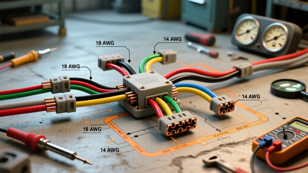
| 18 AWG | 6 Amps | PCM sensors, low-draw LED markers, CAN bus network lines, airbag squibs. |
| 16 AWG | 10 Amps | Standard exterior lighting, horn relays, interior dome lamps, radio constant memory. |
| 14 AWG | 15 Amps | Power windows, power door lock actuators, windshield wiper motor control circuits. |
| 12 AWG | 20 Amps | HVAC blower motors, heated/ventilated seat modules, main ignition feeds (Ckt 40). |
| 10 AWG | 30 Amps | Fuel pump modules, ABS/EBCM main power feeds, trailer brake controller outputs. |
| 8 AWG | 40 Amps | Starter solenoid feeds, high-draw aftermarket amplifiers, cooling fan primary feeds. |
| 4 AWG | 60+ Amps | Alternator main output, battery-to-starter positive cables, EV/Hybrid high-current DC feeds. |
When sourcing replacement wire for a Chevy repair, always specify cross-linked polyethylene (XLPE) insulation (often labeled as GXL or TXL wire). Standard PVC wire (THHN) will melt when routed near the exhaust manifolds of Chevy's 5.3L and 6.2L V8 engines.
Step-by-Step Circuit Tracing in Modern GM Trucks
Reading the wiring diagram for Chevy vehicles is useless if you cannot physically trace the circuit. Modern Silverados and Tahoes use complex Delphi (now Aptiv) Metri-Pack and GT 150/280 connectors. Here is the professional workflow for tracing a dead circuit:
- Identify the Circuit Number: Locate the component on the GM schematic and note the circuit number (e.g., CKT 1432 for a fuel pump control module feed).
- Locate the Physical Connector: Find the component and identify the connector cavity ID. GM diagrams use a grid system (e.g., Connector X1, Pin 4).
- Back-Probe Safely: Never pierce the wire insulation with a test light; this introduces moisture and causes green rot (copper oxidation). Use dedicated back-probing pins that slide past the connector weather-pack seal and contact the terminal blade.
- Verify Power and Ground: Using a high-impedance Digital Multimeter (like the Fluke 87V MAX) or a Power Probe IV, check for battery voltage at the feed pin. Then, check the ground pin. A reading of 12.6V on the power side and less than 0.1V voltage drop on the ground side confirms the harness is intact.
- Check the TPA: If the terminal is dead but the wire has continuity further up the harness, check the Terminal Position Assurance (TPA) lock. On GM GT 280 connectors, a failing TPA clip can allow the terminal to back out slightly, losing contact with the mating pin.
Common Chevy Wiring Failure Modes & Edge Cases
Even with perfect schematics, certain Chevy models suffer from known, repetitive wiring failures. Being aware of these edge cases will save hours of diagnostic time:
- G103 Ground Stud Corrosion (Silverado/Sierra 1500): The main engine-to-chassis ground strap (G103), typically located on the passenger side cylinder head or block, is notorious for corrosion. This causes erratic PCM behavior, stalling, and 5V reference circuit dropouts. Always voltage-drop test the main ground before condemning a PCM.
- Liftgate Harness Chafing (Tahoe/Suburban/Yukon): The wiring boot transitioning from the roof to the rear liftgate frequently cracks. The 18 AWG and 16 AWG wires inside chafe against the metal hinge, causing short-to-ground faults that blow the RAP (Retained Accessory Power) fuses and kill the rear wiper and license plate lamps.
- EBCM Harness Fretting (Mid-2010s Trucks): The heavy 10 AWG and 12 AWG power and ground wires entering the Electronic Brake Control Module (EBCM) connector suffer from fretting corrosion due to engine vibration. This triggers C0561 or C0896 ABS codes. The fix requires cleaning with electrical contact cleaner and applying dielectric grease, not just clearing the codes.
Summary and Upfitter Resources
Mastering the wiring diagram for Chevy vehicles requires moving beyond basic color recognition and understanding the intersection of GM's circuit logic and SAE thermal standards. Always rely on official GM Upfitter Guidelines when adding auxiliary lighting, winches, or secondary batteries to ensure your wire gauge and fuse sizing do not compromise the vehicle's CAN bus architecture. By combining precise schematic reading with proper back-probing techniques and XLPE wire selection, you can diagnose and repair GM electrical systems with dealership-level accuracy.