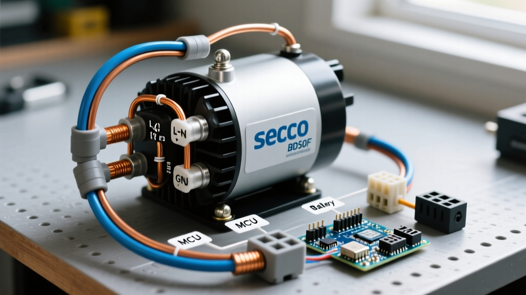

The Heart of Your Off-Grid Cold Chain: 12V Compressor Refrigeration
When outfitting a camper van, skoolie, or travel trailer for off-grid living in 2026, the 12V DC compressor refrigerator has entirely replaced the legacy absorption fridge. Whether you are installing a pre-built unit like the Dometic CFX3 series or building a custom cold-box using a bare Secop (formerly Danfoss) compressor, understanding the exact wiring diagram for fridge compressor integration is critical. A poorly wired 12V compressor will suffer from voltage drop, fail to start under load, or trigger phantom fault codes that ruin your food supply.
This vehicle-specific guide breaks down the exact wiring topology, wire gauge mathematics, and Electronic Control Unit (ECU) pinouts required to run a variable-speed DC compressor reliably on a lithium or AGM house bank.
Anatomy of a 12V Vehicle Fridge Compressor System
Unlike household 120V AC refrigerators that plug into a wall and rely on a simple start-relay, vehicle 12V/24V DC compressors utilize a sophisticated microprocessor-controlled ECU. This module handles the variable frequency drive (VFD) logic, stepping the compressor speed up or down based on thermal demand and available voltage.
Secop BD35F vs. BD50F: Sizing Your Harness
The Secop BD series remains the undisputed industry standard for mobile refrigeration. Before pulling wire, you must identify your compressor model, as the amperage draw dictates your circuit protection and wire gauge.
| Specification | Secop BD35F | Secop BD50F |
|---|---|---|
| Volume Capacity | Up to 250 Liters | Up to 500 Liters |
| Max Current Draw (12V) | ~6.5 Amps | ~10.5 Amps |
| Average Hourly Draw | 1.0 - 2.5 Ah | 1.5 - 3.5 Ah |
| Recommended Fuse (12V) | 15A ATC/ATO Blade | 20A ATC/ATO Blade |
| 2026 Replacement Cost | ~$320 USD | ~$385 USD |
The Core 12V Wiring Diagram for Fridge Compressor Setups
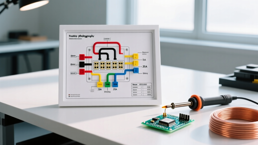
The following step-by-step topology represents the gold standard for mobile DC refrigeration wiring. Never wire the fridge directly to the battery terminals without proper overcurrent protection and a dedicated negative busbar.
Step 1: Battery to Fuse Block (The Main Trunk)
- Overcurrent Protection: Install a 15A or 20A (depending on model) ATC blade fuse or MIDI fuse within 18 inches of the positive battery terminal. This protects the main trunk wire from short-circuit fires.
- Switching (Optional but Recommended): Route the positive trunk through a high-amperage marine-grade rocker switch or a smart BMS-controlled relay. This allows you to kill the fridge during long-term vehicle storage to prevent phantom drain.
- Busbar Integration: Terminate the positive and negative trunk wires at a dedicated, insulated distribution busbar (e.g., Blue Sea Systems 4-stud busbar). Never ground the fridge directly to the vehicle chassis; alternator ripple and chassis corrosion cause severe voltage instability.
Step 2: The Electronic Control Unit (ECU) Module
The Secop ECU is typically mounted directly to the side of the compressor via a spring-loaded retaining clip. The wiring harness plugs into a multi-pin terminal block. Here is the exact pinout configuration for standard mobile installations:
- + (Positive): 12V DC from the positive busbar.
- - (Negative): 12V DC return to the negative busbar.
- C (Common): Jumper wire connected to the Positive (+) terminal. This provides the reference voltage for the thermostat.
- T (Thermostat): Connected to the mechanical or digital thermostat. When the thermostat closes (calling for cooling), it completes the circuit between C and T, signaling the ECU to spin the compressor.
- D (Door Switch): Optional. Connects to a microswitch on the fridge door. When the door opens, it triggers a small voltage drop that turns on the interior LED light and can be programmed to reduce compressor speed to save energy.
- P (Protection/LED): Connects to a diagnostic LED indicator mounted on the exterior of the fridge cabinet.
Expert 2026 Integration Tip: If you are using a modern Victron Energy Cerbo GX or Redarc BMS, you can wire the ECU's diagnostic output to a digital input on your BMS. This allows your central monitoring screen to read fridge compressor RPM and fault states in real-time over the vehicle's CAN bus network.
Wire Gauge & Voltage Drop: The Silent Fridge Killer
The most common reason a 12V compressor fridge fails to start in a camper van is voltage drop. DC compressors require a minimum of 10.4V at the ECU terminals to initiate the motor startup sequence. If your wire is too thin or the run is too long, the voltage at the ECU will sag below this threshold during the high-torque startup phase, causing the ECU to abort and throw a fault code.
Consult the Blue Sea Systems Circuit Protection Guide for comprehensive DC wire sizing standards. Below is the specific wire gauge matrix for Secop BD series compressors based on total circuit length (Positive + Negative wire combined).
| Total Wire Run Length | BD35F (Max 6.5A) | BD50F (Max 10.5A) |
|---|---|---|
| Under 10 Feet | 12 AWG | 10 AWG |
| 10 to 20 Feet | 10 AWG | 8 AWG |
| 20 to 35 Feet | 8 AWG | 6 AWG |
| Over 35 Feet | 6 AWG | 4 AWG |
Note: Always use pure copper, multi-strand marine-grade wire (Type 3 UL 1426). Copper-clad aluminum (CCA) wire has higher resistance and will cause severe voltage drop in low-voltage DC vehicle systems.
Integrating the Thermostat and LED Fault Codes
While many modern 12V fridges use digital thermistors, custom builds often utilize a standard mechanical capillary thermostat. The wiring is simple: run a 2-conductor 18 AWG wire from the ECU's C and T terminals to the thermostat. The polarity does not matter on a standard mechanical switch.
Decoding the ECU Diagnostic LED
When troubleshooting, the LED connected to the P terminal will flash a specific number of times, followed by a pause. This is your primary diagnostic tool. According to Secop DC Compressor Documentation, the flash codes indicate the following:
- 1 Flash: Thermostat short circuit or ECU internal fault.
- 2 Flashes: Fan overcurrent. The condenser fan is drawing too much power (usually due to debris blocking the fan blade or a failing fan motor).
- 3 Flashes: Motor start failure. The rotor is locked, or voltage drop is preventing startup. Check your wire gauge and battery state of charge.
- 4 Flashes: Speed too low. The control system cannot maintain the minimum RPM, often caused by excessive thermal load or low refrigerant.
- 5 Flashes: Overheat cutout. The ECU heat sink is too hot. Improve ventilation around the compressor housing.
Common Vehicle-Specific Failure Modes & Troubleshooting
Alternator Whine and Ground Loops
If you hear a high-pitched whining noise through your vehicle's stereo system when the fridge compressor kicks on, you have created a ground loop. This happens when the fridge's negative return path shares a chassis ground with the audio amplifier. The Fix: Isolate the fridge ground. Run a dedicated negative wire all the way back to the house battery negative busbar, adhering to ABYC Technical Standards for DC system isolation.
Voltage Sag During Engine Cranking
In camper vans where the house bank is tied to the chassis battery via a VSR (Voltage Sensitive Relay) or DC-DC charger, cranking the engine can cause system voltage to momentarily drop below 9V. While the Secop ECU has built-in low-voltage cutout protection, repeated voltage sags can corrupt the ECU's EEPROM memory over time. Always use a DC-DC charger with a dedicated "fridge" output or install a voltage-stabilizing capacitor module inline with the fridge's positive feed to buffer transient cranking sags.
Condenser Airflow Starvation
Vehicle cabinets are notoriously tight. If you build a custom enclosure for the fridge, you must provide a minimum of 40 square inches of intake venting and 40 square inches of exhaust venting. For BD50F compressors, installing a 12V PC-style exhaust fan wired in parallel with the compressor's fan circuit will drop the ambient temperature around the ECU by up to 15°F, drastically reducing the occurrence of 5-flash overheat faults during desert boondocking.