
Understanding the Sno-Way MT Multiplex Architecture
When consulting a wiring diagram for Sno Way plow systems, particularly the flagship Multiplex Technology (MT) series, you are looking at a sophisticated network that replaces traditional heavy relay banks with solid-state multiplexing. Manufactured by Douglas Dynamics, the MT system utilizes a Controller Area Network (CAN) bus-style data loop to communicate between the in-cab control module and the plow-mounted power unit. This drastically reduces the physical wire count required to pass through the firewall and vehicle bulkhead.
As of early 2026, the MT system remains the industry standard for commercial snow removal fleets due to its solid-state reliability and integrated diagnostics. However, because it relies on high-speed data signals alongside heavy-draw hydraulic solenoid power, improper wire gauge selection or poor termination will result in 'No Com' errors or solenoid chatter. This guide breaks down the exact pinouts, routing specifications, and diagnostic procedures required for a flawless installation or repair.
CRITICAL SAFETY WARNING: Always disconnect the negative battery terminal before cutting, splicing, or routing any plow harness wires. The MT system's main power circuit carries up to 150 Amps; a short circuit without proper overcurrent protection can instantly weld tools to the chassis and ignite a vehicle fire.
13-Pin Vehicle-to-Plow Connector Pinout Matrix
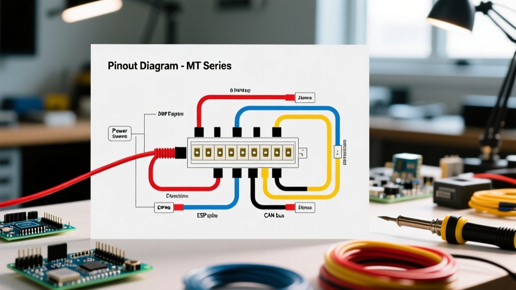
The physical interface between the truck and the plow relies on a ruggedized 13-pin round connector. Unlike older 7-pin systems that dedicated individual pins to every hydraulic valve, the MT system uses data pins to command the plow-side multiplex module. Below is the standard pinout configuration for the 2025/2026 MT harnesses.
| Pin | Function | Wire Color (Typical) | Gauge / Specification |
|---|---|---|---|
| A | System Ground | Black | 10 AWG |
| B | Right Turn / Hazard | Brown | 14 AWG |
| C | Left Turn / Hazard | Yellow | 14 AWG |
| D | Tail / Marker Lights | Green | 14 AWG |
| E | High Beam Headlights | White | 14 AWG |
| F | Low Beam Headlights | Blue | 14 AWG |
| G | Lighting Ground | Black | 14 AWG |
| H | Multiplex Data + (CAN High) | Red w/ White Tracer | 18 AWG (Twisted Pair) |
| J | Multiplex Data - (CAN Low) | Black w/ White Tracer | 18 AWG (Twisted Pair) |
| K | Ignition Sense / 12V Accessory | Red | 14 AWG |
| L | Main Power (Solenoid Trigger) | Red (Heavy) | 6 AWG or 4 AWG |
| M | Auxiliary / Spare | Orange | 14 AWG |
Heavy-Duty Power and Ground Routing Specifications
The most common point of failure in any plow installation is voltage drop on the main power and ground circuits. The hydraulic pump motor on a Sno-Way MT system can draw upwards of 120 Amps under heavy load (e.g., when stacking dense, wet snow).
Wire Gauge Selection by Run Length
According to National Truck Equipment Association (NTEA) upfitter guidelines, voltage drop must be kept below 3% for high-draw DC motors. Use the following sizing rules for Pin L (Main Power) and the main chassis ground:
- Under 10 Feet (Total Round Trip): Use 6 AWG stranded copper wire.
- 10 to 15 Feet: Use 4 AWG stranded copper wire.
- Over 15 Feet (e.g., extended wheelbase crew cabs): Use 2 AWG stranded copper wire.
Terminal Crimping and Overcurrent Protection
Do not use solder on high-current battery terminals; solder can become brittle under the vibration of a diesel engine and plow impacts. Instead, use a hydraulic or heavy ratcheting crimper to attach closed-loop ring terminals. Install a 150-Amp Mega Fuse within 18 inches of the positive battery post. This protects the entire harness in the event of a dead short against the vehicle frame.
Multiplex Data Line (CAN Bus) Wiring & Termination
Pins H and J carry the multiplex data signals. These are low-voltage, high-frequency square waves that are highly susceptible to electromagnetic interference (EMI) from the vehicle's alternator and ignition system.
- Twisted Pair Routing: The Data + and Data - wires must remain twisted together right up to the terminal pins. Do not untwist more than 1 inch of wire at the connector backshell.
- Separation from Power: Route the 18 AWG data wires at least 6 inches away from the 6 AWG main power wire and away from the engine's spark plug wires or high-output alternator stator wiring.
- Shielding: If running through a high-EMI area (such as near an aftermarket inverter or heavy-duty radio transmitter), use a shielded twisted-pair (STP) cable and ground the shield drain wire at the cab module end only.
Step-by-Step Cab Control Integration
The in-cab control module requires three basic connections to wake up and initiate the plow sequence:
- Constant 12V Memory: Connect to a fused battery source (typically 5A) to retain diagnostic codes and settings.
- Ignition Sense (Pin K): Connect to a circuit that is hot only in the 'Run' and 'Start' positions. This prevents the plow module from draining the battery if the operator forgets to turn off the cab controller.
- Cab Ground: Ground the module directly to a clean, unpainted metal surface on the vehicle's dash support frame. Avoid grounding to plastic-backed dash panels or shared ground buses that carry high-current accessories like heated seats.
Diagnostic Troubleshooting: Multimeter & Oscilloscope Guide
When the Sno-Way MT display flashes an error code, or the plow fails to respond, use a digital multimeter (DMM) to isolate the fault. As noted by Sno-Way International technical service bulletins, over 70% of 'No Com' errors are caused by physical connector issues rather than failed modules.
| Symptom / Error Code | Electrical Test Procedure | Expected Result & Fix |
|---|---|---|
| 'No Com' on Cab Display | Measure resistance between Pin H and Pin J at the vehicle harness (plow disconnected). | Should read approx. 60 to 120 ohms (depending on termination resistors). If open (OL), check for broken data wires in the harness flex loop. |
| Solenoid Clicks but Motor Won't Turn | Perform a voltage drop test on the main ground cable while the solenoid is engaged. | Drop must be < 0.2V. If higher, clean the chassis ground bolt or replace the 6 AWG cable. The motor is starved of return current. |
| Plow Drifts Down Slowly | Check voltage at the 'Hold' valve coil connector on the pump unit while raised. | Should read 0V when off, 12V when raised. If voltage is present but plow drops, the valve spool is mechanically contaminated, not an electrical fault. |
| Lights Flicker on Bumps | Wiggle test on Pins B, C, D, E, F while monitoring resistance to Pin G. | Resistance should remain near 0.1 ohms. Flickering indicates loose pin crimps inside the 13-pin overmold. Replace the vehicle-side pigtail. |
Winterization and Dielectric Maintenance
Moisture intrusion is the enemy of the 13-pin connector. Road salt creates a highly conductive brine that can bridge the gap between the 12V ignition pin and the low-voltage CAN bus pins, frying the cab module's internal transceiver chip.
Before the first snowfall of the 2026 season, unplug the 13-pin connector and inspect the rubber seal ring. Apply a generous coating of Nyogel 760G or a high-quality silicone dielectric grease to the pins. Do not use standard lithium grease or Vaseline, as these can degrade the rubber seals and attract abrasive grit. Furthermore, always use the dummy plug (dust cap) on the vehicle harness when the plow is detached to prevent salt spray from corroding the exposed terminals.
Expert Tip: The 'Flex Loop' Failure Point
The section of the harness that loops between the truck bumper and the plow A-frame undergoes thousands of articulation cycles. Inspect this 'flex loop' for micro-fractures in the outer jacket. If the outer jacket is cracked, moisture has already wicked into the copper strands via capillary action. In these cases, splicing is a temporary band-aid; replacing the entire vehicle-side harness (typically $210 to $260 for OEM MT harnesses in 2026) is the only reliable long-term solution. For deeper automotive wiring standards and upfitter safety protocols, technicians should refer to the SAE International J1128 and J1113 standards for low-tension wiring and electromagnetic compatibility.