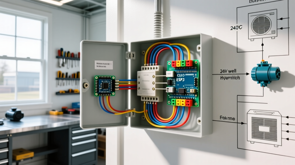

Decoding the Mobile Home Electrical Panel Wiring Diagram
Wiring heavy inductive loads in a manufactured home requires a precise understanding of both the physical panel layout and the governing electrical codes. Unlike traditional stick-built homes, mobile homes are governed by a unique intersection of the National Electrical Code (NEC) and the Department of Housing and Urban Development (HUD) manufactured housing standards. When you examine a mobile home electrical panel wiring diagram, you are typically looking at a 100A to 200A load center—commonly a Square D Homeline HOM816L125TC or a Siemens W0408ML1125.
While standard 15A and 20A branch circuits for lighting and receptacles are straightforward, integrating 240V motor loads (such as well pumps, HVAC compressors, and workshop equipment) introduces complex variables. These include Locked Rotor Amps (LRA), voltage drop over long exterior runs, and strict neutral-to-ground separation rules. This guide bridges the gap between reading your panel's schematic and executing a flawless, code-compliant motor wiring installation in 2026.
Anatomy of the Manufactured Home Load Center
Before pulling any wire, you must determine if your interior panel is functioning as a service disconnect (main panel) or a subpanel. This distinction dictates how you terminate your neutral and ground wires, which is the most common failure point in mobile home electrical systems.
- Main Panel Configuration: If the utility feeder connects directly to this interior panel with no exterior disconnect, the neutral and ground bars must be bonded. The diagram on the panel door will show a green bonding screw or strap connecting the neutral bus to the panel enclosure.
- Subpanel Configuration: If your mobile home has an exterior disconnect pedestal (common in modern mobile home parks per NEC Article 550), the interior panel acts as a subpanel. The neutral and ground bars must remain isolated. The wiring diagram will depict the neutral bus floating on insulators, while the ground bus is bonded directly to the metal chassis.
Critical Safety Warning: Never bond the neutral and ground in a mobile home interior subpanel. Doing so creates a parallel neutral path through the home's metal chassis and the exterior grounding conductor, posing a severe shock hazard and violating HUD Manufactured Home Construction and Safety Standards.
Sizing Breakers and Wire for Motor Loads (NEC Article 430)
Standard branch circuit rules (NEC Article 210) do not apply to motors. Motors draw massive inrush currents during startup. If you size a breaker based purely on the motor's Full Load Amps (FLA), it will trip every time the motor starts. Instead, you must follow NEC Article 430, which allows for specific overcurrent protection multipliers.
The 125% and 250% Rules Explained
- Conductor Sizing (125% Rule): Motor branch circuit conductors must be sized at no less than 125% of the motor's FLA. For a 3HP, 240V well pump with an FLA of 17A, the wire must handle at least 21.25A (17 x 1.25).
- Breaker Sizing (250% Rule): For inverse-time circuit breakers (standard residential breakers), NEC 430.52 permits sizing up to 250% of the FLA to accommodate startup surges. For our 17A motor, the maximum standard breaker size is 40A (17 x 2.5 = 42.5, rounded down to the nearest standard size of 40A).
Pro Tip: Always defer to the motor manufacturer's nameplate. If the nameplate specifies a 'Maximum Overcurrent Protection' (MOCP) of 30A, you cannot use a 40A breaker, even if NEC 430 theoretically allows it. The manufacturer's listed instructions override general code tables.
Step-by-Step Tutorial: Wiring a 240V Well Pump Motor
Let's apply the mobile home electrical panel wiring diagram to a real-world scenario: wiring a 3HP, 240V submersible well pump located 80 feet from the mobile home's interior panel.
Step 1: Select the Conductor and Conduit
Based on the 125% rule (21.25A minimum), 10 AWG copper THHN/THWN-2 (rated for 35A at 75°C) is technically sufficient. However, because the run is 80 feet, we must calculate voltage drop. A 3% maximum voltage drop on a 240V circuit allows for a 7.2V drop. Using 10 AWG copper over 80 feet at 17A yields a 2.4% drop, which is acceptable. In 2026, with 10 AWG THWN-2 averaging $0.45 per foot, this is cost-effective. Run the wires through 3/4-inch Liquidtight Flexible Metallic Conduit (LFMC) for the exterior transition.
Step 2: Install the Double-Pole Breaker
Install a 30A double-pole breaker (e.g., Square D HOM230) into the panel. Ensure the breaker seats fully onto both hot bus bars. Torque the terminal lugs to the manufacturer's specification—typically 20 in-lbs for 10-8 AWG wire on Homeline panels. Under-torqued lugs cause high-resistance connections, leading to thermal melting and fire.
Step 3: Route and Terminate at the Disconnect
NEC requires a local disconnecting means within sight of the motor controller. Mount a 60A non-fusible pull-out disconnect box near the wellhead. Terminate the two hot wires (Black and Red) to the line side of the disconnect. Connect the bare copper ground to the disconnect's grounding lug. Do not run a neutral wire for a pure 240V motor load.
Step 4: Wire the Motor Controller
From the load side of the disconnect, run wires to the motor control box (which houses the capacitor and pressure switch). Follow the NEMA MG 1 motor wiring standards for the specific terminal designations (typically T1, T2, T3 for three-wire setups, or L1, L2 for single-phase 240V).
Motor Load Sizing Matrix for Mobile Home Panels
Use this reference table for common 240V single-phase motors integrated into residential mobile home panels. Data assumes a maximum ambient temperature of 30°C and copper conductors.
| Motor HP | Approx. FLA (240V) | Min. Wire Size (125% FLA) | Max Standard Breaker (250% FLA) | Typical Nameplate MOCP |
|---|---|---|---|---|
| 1.5 HP | 10.0A | 14 AWG (Use 12 AWG min) | 25A | 20A or 25A |
| 2.0 HP | 12.0A | 12 AWG | 30A | 25A or 30A |
| 3.0 HP | 17.0A | 10 AWG | 40A | 30A or 35A |
| 5.0 HP | 28.0A | 8 AWG | 70A | 50A or 60A |
Edge Cases and Common Failure Modes
Even with a perfect schematic, real-world conditions in mobile home parks introduce unique failure modes. Watch out for these specific issues:
- Undersized Feeder Voltage Drop: If the mobile home park's feeder from the utility transformer to your exterior pedestal is undersized, the baseline voltage at your panel might already be 228V instead of 240V. Adding a large motor load will cause the voltage to sag below 216V during startup, causing the motor's internal thermal overload to trip repeatedly. Solution: Upgrade the feeder or install a soft-start kit on the motor.
- Shared Neutral Miswiring: When adding a 120/240V appliance (like a dryer) near a 240V motor, apprentices sometimes attempt to share a neutral or ground path. Motor circuits do not utilize a neutral; mixing multi-wire branch circuit (MWBC) rules with pure motor circuits will result in immediate code violations and potential neutral overload.
- Corroded Bus Bars: Mobile homes are prone to higher humidity and condensation inside wall cavities. If your panel is located in a utility closet near the water heater, inspect the bus bars for zinc oxide buildup (white powder). This increases contact resistance and causes breakers to overheat under sustained motor loads.
Frequently Asked Questions (FAQ)
Can I use aluminum wire for motor circuits in a mobile home?
While aluminum SER cable is commonly used for the main feeder to a mobile home, branch circuits for motors should ideally use copper THHN/THWN-2. Aluminum is more susceptible to thermal expansion and contraction, which can loosen connections at the motor's vibration-heavy terminals over time. If you must use aluminum, you must apply an antioxidant compound (like Noalox) and use lugs specifically rated for AL/CU.
Does a mobile home HVAC condenser require a GFCI breaker in 2026?
Under the latest adopted NEC cycles, outdoor outlets and specific HVAC equipment require GFCI protection. However, hardwired HVAC compressors connected via a dedicated disconnect switch are generally exempt from GFCI breaker requirements unless specifically mandated by local amendments or if the unit is installed as a plug-in cord-connected appliance. Always verify with your local Authority Having Jurisdiction (AHJ).
How do I balance the panel when adding a large motor?
A 240V motor draws equally from both the A-phase and B-phase bus bars, so it inherently balances itself across the panel. However, ensure that your existing 120V loads (lights, receptacles) are evenly distributed between the two hot legs to prevent the neutral bus from carrying excessive unbalanced current.