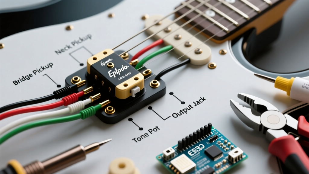

Planning Your Epiphone Les Paul Rewire: Beyond the Basic Schematic
Upgrading the electronics in an Epiphone Les Paul is one of the most transformative modifications you can perform. While the factory wiring is generally functional, it often relies on metric Alpha potentiometers, ceramic disc capacitors, and thin PVC-coated wire that can sap high-end clarity and introduce microphonic feedback. If you are searching for a reliable wiring diagram for Epiphone Les Paul models, you are likely preparing for a pickup swap or a full harness overhaul. This installation planning guide goes beyond a simple visual schematic, providing the exact luthier specifications, tool requirements, and failure-mode preventions necessary for a professional-grade installation in 2026.
The Metric vs. Imperial Conundrum: Critical Pre-Installation Planning
Before you even look at a wiring diagram, you must address the physical hardware differences between Epiphone and Gibson Les Paul models. This is the number one point of failure for DIY guitar techs.
- Potentiometer Shaft & Hole Size: Epiphone uses metric import pots with a 6mm (approx. 0.236-inch) shaft diameter and an 18-spline knurling. Standard US-spec CTS pots have a 0.250-inch (6.35mm) shaft and 24-spline knurling. Furthermore, the mounting hole in an Epiphone body is drilled for 6mm. You must ream the body holes to 3/8-inch (9.52mm) to install premium CTS pots.
- Toggle Switch Routing: Many modern Epiphone Les Paul Standards use a short-body import toggle or an Asian-spec right-angle switch. Upgrading to a Switchcraft #12A long-body or #12AA short-body requires verifying the control cavity routing depth and the thickness of the maple cap.
- Knob Compatibility: Because of the spline difference, your factory Epiphone speed knobs will not fit US-spec CTS pots. You must budget for new 24-spline knobs (like Gibson USA top-hats or custom metal domes).
2026 Component Selection & Budgeting Matrix
Building a premium wiring harness requires sourcing high-tolerance components. Below is a comparison of factory Epiphone parts versus the recommended upgrade path, complete with current 2026 market pricing.
| Component | Factory Epiphone Spec | Premium Upgrade (Recommended) | Est. 2026 Price (USD) |
|---|---|---|---|
| Volume/Tone Pots | 500k Metric Alpha (Audio) | CTS 450G 500k Audio Taper (Long Split Shaft) | $8.50 each |
| Capacitors | Generic 0.047µF Ceramic Disc | Sprague Orange Drop 225P 0.022µF 100V | $4.00 each |
| Toggle Switch | Import Short-Body / Right-Angle | Switchcraft #12AA Short Toggle (Nickel) | $14.50 |
| Output Jack | Generic Open-Frame Mono | Switchcraft #11 Mono Jack (Nickel) | $6.00 |
| Hookup Wire | 24 AWG PVC Stranded | 22 AWG Tinned Copper (Ground) / 24 AWG Push-Back (Signal) | $12.00 / spool |
Luthier Pro-Tip: For humbuckers, a 0.022µF capacitor is the industry standard, providing a smooth, musical roll-off of high frequencies. If you want a darker, more vintage 'Woman Tone' on the neck pickup, consider using a 0.015µF capacitor on the neck tone control while keeping 0.022µF on the bridge.
Decoding the Wiring Diagram: Node-by-Node Breakdown
While visual schematics from manufacturers like Seymour Duncan are excellent references, understanding the logical flow of the nodes is crucial for troubleshooting. The standard Epiphone Les Paul circuit features independent volume and tone controls for each pickup, wired in a 'modern' or '50s' configuration. We recommend the Modern Wiring configuration for most players, as it prevents the volume from rolling off high-end frequencies when you lower the tone pot.
1. The Volume Potentiometer Nodes
For both the Neck and Bridge volume pots (500k Audio Taper):
- Lug 1 (Left): Connect to the respective tone potentiometer (Lug 1) and the output jack tip.
- Lug 2 (Middle): This is the 'hot' input. Solder the hot lead (typically white or bare braided shield depending on the pickup brand) from your 3-way toggle switch here.
- Lug 3 (Right): Ground. Solder this directly to the back casing of the volume pot.
2. The Tone Potentiometer Nodes
- Lug 1 (Left): Connect to Lug 1 of the corresponding volume pot.
- Lug 2 (Middle): Solder one leg of the 0.022µF capacitor here. (The other leg of the capacitor is soldered to the back casing of the tone pot, completing the circuit to ground).
- Lug 3 (Right): Not used in modern wiring. Bend it back or snip it off to prevent accidental shorting.
3. The 3-Way Toggle Switch (Switchcraft Style)
- Top Lug (Neck): Hot out to Neck Volume Pot (Lug 2).
- Bottom Lug (Bridge): Hot out to Bridge Volume Pot (Lug 2).
- Two Middle Lugs: Jumper these together and run a single wire to the Output Jack Tip.
- Base/Frame: Ground wire to the back of the Bridge Volume Pot.
Essential Tools & Workspace Preparation
A successful harness build relies heavily on thermal management. Potentiometer casings act as massive heat sinks. If your iron is underpowered, you will hold the iron to the casing too long, melting the internal phenolic track and ruining a $9 CTS pot.
- Soldering Station: A temperature-controlled station (like the Hakko FX-888D or Weller WE1010NA) set between 700°F and 750°F (370°C - 400°C).
- Solder: 60/40 or 63/37 Rosin-Core, 0.031-inch diameter. Avoid acid-core plumbing solder at all costs. For detailed guidance on proper soldering techniques, refer to the StewMac Soldering Guide.
- Flux: No-clean tacky flux (e.g., MG Chemicals 8341) is mandatory for grounding to pot casings and switch frames.
- Reamer Tool: A 3/8-inch (9.52mm) hand reamer for enlarging the Epiphone body holes. Do not use a standard drill bit, as it will chip the maple cap and tear the mahogany.
Step-by-Step Installation Execution Plan
Phase 1: The 'Baking Pan' Pre-Wire
Never solder inside the guitar cavity if you can avoid it. The risk of dropping a blob of molten solder onto the delicate nitrocellulose or polyurethane finish is too high. Instead, build the entire harness outside the guitar on a template.
- Print a 1:1 scale wiring diagram and place it inside a metal baking pan or on a silicone soldering mat.
- Place your pots, switch, and jack in their respective geometric positions on the template.
- Scuff the backs of all potentiometer casings with 220-grit sandpaper and apply a dab of flux. Pre-tin the casings with a small puddle of solder.
- Cut your 22 AWG ground wires to length, strip 1/4-inch of insulation, tin them, and solder the daisy-chain grounds: Bridge stud wire -> Neck Vol -> Bridge Vol -> Neck Tone -> Bridge Tone -> Jack Sleeve.
- Solder the signal wires and capacitors. Keep soldering time on pot lugs under 3 seconds to prevent heat transfer to the resistive track.
Phase 2: Threading and Cavity Installation
- Attach a small piece of tubing or a straw to the shaft of each pot to protect it, then tie a sturdy piece of nylon string or use a dedicated pot-puller tool.
- Feed the string through the control cavity holes and out the top of the guitar. Gently pull the pots through the holes. Never pull on the delicate signal wires to guide the pot into place.
- Install the switch and jack. Ensure the Switchcraft jack's longer lug (tip) does not touch the bare wood or shielding paint, which will short out the signal.
Common Failure Modes & Edge Case Troubleshooting
Even with a perfect wiring diagram for your Epiphone Les Paul, physical installation variables can introduce faults. Here is how to diagnose the most common post-installation issues:
1. The 'Ground Loop' Hum
Symptom: The guitar hums loudly, and touching the strings or metal hardware does not reduce the noise; it might even increase it.
Cause: You have created multiple paths to ground, or the bridge ground wire is not making contact with the tailpiece stud.
Fix: Ensure the bare copper wire routed from the control cavity to the bridge post hole is firmly pinched against the metal stud when you press it into the wood. Verify that your output jack is not reversed (tip and sleeve swapped).
2. Out-of-Phase 'Quack' in the Middle Position
Symptom: The neck and bridge pickups sound great individually, but when the toggle is in the middle position, the sound is thin, hollow, and lacks bass.
Cause: The magnetic polarity or electrical phase of one pickup is reversed relative to the other. This often happens when mixing pickup brands (e.g., a Seymour Duncan bridge with a DiMarzio neck).
Fix: Swap the hot and ground leads on one of the pickups at the volume pot. If the pickup has a braided shield, you will need to isolate the shield from ground and run a dedicated ground wire, or simply swap the magnet orientation inside the pickup cover if you are comfortable with physical teardowns.
3. Scratchy Potentiometers Post-Solder
Symptom: The volume or tone pot crackles violently when turned.
Cause: Heat damage to the carbon track during soldering, or flux residue seeped into the pot casing.
Fix: If flushing with DeoxIT D5 does not resolve the issue, the phenolic track is permanently burned. You must desolder and replace the component. Always use a heat sink (like a hemostat clamped to the lug) or keep your iron contact time strictly under 3 seconds.
Final Verification and Setup
Before restringing the guitar and plugging into a high-gain amplifier, use a digital multimeter set to continuity mode. Touch one probe to the bridge and the other to the sleeve of the output jack. You should hear a continuous beep, confirming your chassis ground is intact. Next, check for shorts by touching the multimeter probes to the jack tip and sleeve; it should read an open circuit (OL) when the volume pots are at zero, and roughly 250k-500k ohms when the volume pots are at 10 (depending on your pickup DC resistance). By treating your Epiphone Les Paul rewire as a precision electronics project rather than a simple swap, you will unlock the full tonal potential, dynamic range, and reliability of your instrument for decades to come.