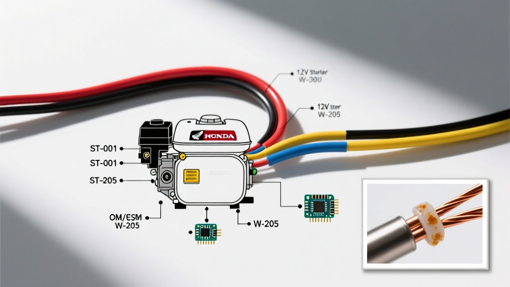

Decoding the Honda GX390 Electric Start Circuit
The Honda GX390 is a 389cc, 11.7 HP commercial-grade engine widely used in pressure washers, generators, and heavy-duty water pumps. While the recoil pull-start is reliable, the electric start variant (often designated with an 'ET' or 'E' suffix) adds a 12V DC starter motor and a charging coil to maintain the battery. Understanding the official Honda GX390 electric start wiring diagram PDF is critical for diagnosing no-crank conditions, upgrading from a recoil model, or integrating the engine into a custom machine's 12V control panel.
In this 2026 reference guide, we break down the exact OEM wiring topology, standard Honda wire color codes, precise multimeter testing procedures, and the real-world costs of replacement components.
Anatomy of the GX390 12V Starter System
Before tracing wires, you must identify the core components in the electric start loop. The GX390 utilizes a 12V, 0.4 kW starter motor paired with an external heavy-duty solenoid to prevent high amperage from frying the ignition switch. Below is the definitive component matrix with current 2026 OEM part numbers and average retail pricing.
| Component | OEM Part Number | Function | Est. Price (2026) |
|---|---|---|---|
| Starter Motor | 31200-ZE3-013 | Engages flywheel ring gear (80-120A draw) | $145 - $165 |
| Starter Solenoid | 35300-ZE3-003 | Relays high current from battery to starter | $40 - $55 |
| Ignition Switch | 35250-ZE3-020 | 4-pin rotary switch (Start, Run, Off, Ground) | $35 - $45 |
| Voltage Regulator | 31600-ZE3-003 | Converts AC coil output to 12V DC (3A limit) | $30 - $40 |
| Charging Coil | 31120-ZE3-010 | Generates AC power under flywheel magnets | $65 - $85 |
Expert Note: Never bypass the starter solenoid by wiring the ignition switch directly to the starter motor. The GX390 starter draws up to 120 amps during initial cranking. A standard 4-pin ignition switch is rated for only 10-15 amps and will melt internally within seconds.
Honda Standard Wire Color Codes
Honda Power Equipment adheres to a strict color-coding schema across its GX commercial series. When referencing your wiring diagram PDF, match these colors to ensure proper polarity and circuit routing:
- Black (B): Ground / Negative (-). Connects to the engine block or battery negative.
- Red (R): Battery Positive (+). Carries 12V from the battery to the solenoid main terminal.
- Yellow (Y): AC Output. Carries raw alternating current from the stator/charging coil to the voltage regulator.
- White (W): DC Output. Carries regulated 12V DC from the regulator to the battery positive terminal.
- Black/Yellow (B/Y): Ignition Kill. Grounds the ignition coil to stop the engine. Must remain ungrounded during 'Run' and 'Start'.
Step-by-Step Wiring Walkthrough
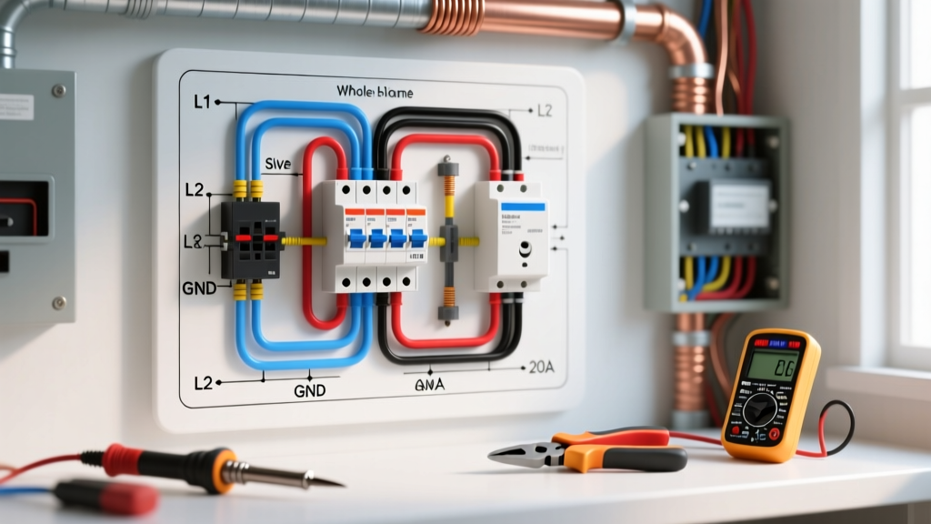
Whether you are building a custom control panel or repairing a chewed wiring harness, follow this sequential routing guide based on the OEM schematic.
1. The High-Current Cranking Circuit
- Run a 10 AWG red wire from the battery positive terminal to the 'B' (Battery) terminal on the starter solenoid.
- Run a second 10 AWG red wire from the 'M' (Motor) terminal on the solenoid directly to the spade terminal on the GX390 starter motor.
- Ensure the starter motor body has a clean, bare-metal ground connection to the engine crankcase. The GX390 starter grounds through its mounting bolts, not via a dedicated wire.
2. The Low-Current Control Circuit
- Run a 14 AWG red wire from the solenoid's 'B' terminal (or directly from the battery) to the 'B' pin on the 4-pin ignition switch.
- Run a 14 AWG white wire from the 'S' (Start) pin on the ignition switch to the 'S' trigger terminal on the solenoid. When the key is turned to START, this completes the solenoid's internal electromagnet circuit, engaging the heavy contacts.
3. The Charging & Kill Circuit
- Connect the Yellow wire from the engine's charging coil to the AC input terminal on the voltage regulator.
- Connect the White wire from the regulator's DC output to the battery positive terminal. This provides a 3-amp trickle charge to offset the cranking draw.
- Connect the Black/Yellow wire from the ignition switch's 'G' (Ground) terminal to the engine's ignition coil kill terminal. When the key is turned to OFF, this wire grounds the coil, collapsing the spark.
Upgrading from Recoil to Electric Start
A highly common DIY project in 2026 is converting a standard GX390 recoil engine to electric start. This is not a simple bolt-on job. According to Honda's official GX390 engineering specifications, the internal and external hardware differs significantly between recoil and electric models.
Required Conversion Components:
- Electric Start Flywheel (Part #21710-ZE3-000): The standard recoil flywheel lacks the machined steel ring gear required for the starter bendix to engage. ($180)
- Starter Motor Bracket & Hardware: If your specific crankcase casting lacks the pre-drilled and tapped mounting bosses for the starter motor, you may need to drill and tap M8x1.25 threads into the crankcase using a precision jig.
- 12V Battery & Tray: A minimum 14Ah sealed lead-acid (SLA) battery is required to handle the 120A peak cranking load without severe voltage sag.
Real-World Troubleshooting & Failure Modes
When the wiring diagram doesn't match the engine's behavior, use these advanced diagnostic steps to isolate the fault.
Symptom: Solenoid Clicks, But Engine Won't Crank
This indicates the low-current control circuit is functioning, but the high-current path is failing due to voltage drop.
- The Test: Set your digital multimeter to DC Volts. Place the red probe on the solenoid's 'B' terminal and the black probe on the 'M' terminal.
- The Action: Have an assistant turn the key to START. Under load, the meter should read less than 0.5V. If it reads 8V to 12V, the internal copper contacts inside the solenoid are pitted and burned. Replace the solenoid (Part #35300-ZE3-003).
Symptom: Battery Drains Overnight
The GX390's 3-amp charging system uses a simple half-wave rectifier inside the voltage regulator. If a diode fails in the 'open' position, the battery will back-feed 12V DC into the stator coil when the engine is off, draining the battery in 12-24 hours.
- The Test: Disconnect the White DC output wire from the regulator. Set the multimeter to Diode Test mode. Place the red probe on the regulator's DC terminal and the black probe on the regulator's mounting tab (ground). It should read 'OL' (Open Line). If it reads a voltage drop (e.g., 0.400V), the internal diode is shorted. Replace the regulator.
Symptom: Engine Cranks, But Will Not Shut Off
If the key is turned to OFF but the engine continues to run, the Black/Yellow kill wire is failing to ground the ignition coil. This is often caused by a sheared flywheel key altering the ignition timing, or a broken Black/Yellow wire between the switch and the coil. Verify continuity between the ignition coil's primary terminal and the engine block when the key is in the OFF position.
Sourcing the Official OEM Diagram PDF
While aftermarket manuals often contain simplified or incorrect schematics, it is vital to use the factory documentation for commercial equipment integration. You can download the authentic Honda GX390 wiring diagram PDF and the complete owner's manual directly from the Honda Power Equipment Manual Portal. Always search using your engine's exact serial number (located on the side of the engine shroud or the crankcase base) to ensure you receive the diagram matching your specific production run, as Honda occasionally updates regulator pinouts between manufacturing years.
For broader electrical safety and wire gauge compliance when integrating the GX390 into larger industrial panels, refer to the National Fire Protection Association (NFPA) guidelines regarding low-voltage DC control circuits and vibration-resistant wire terminations.