
Most DIYers and junior technicians look at a wiring diagram for home thermostat setups and only see low-voltage alphabet soup: R, C, W, Y, G. However, from a comprehensive electrical perspective, the 24-volt control circuit is merely the tail end of a robust 120V or 240V branch circuit originating at your main breaker panel. If you do not understand the high-voltage side of the equation, troubleshooting low-voltage thermostat failures becomes a guessing game.
In this guide, we bridge the gap between the main electrical panel, the HVAC equipment disconnects, the step-down transformers, and the thermostat backplate. Whether you are upgrading to a smart thermostat or diagnosing a dead system, understanding the full circuit path is mandatory for safe, code-compliant electrical work.
The Breaker Panel: Where the Thermostat Circuit Actually Begins
A typical central HVAC system is a split system, meaning it requires two distinct branch circuits from your main electrical panel. The thermostat acts as the logical switch that signals these high-voltage circuits to engage via relays and contactors.
1. The Indoor Air Handler or Furnace Circuit (120V)
The indoor blower motor, control board, and the crucial step-down transformer are powered by a standard 120V single-pole breaker. Depending on the unit's amperage draw and electric heat strips, this is typically a 15-amp or 20-amp breaker using 14 AWG or 12 AWG NM-B (Romex) cable. This circuit provides the primary voltage that the transformer steps down to 24VAC to power your thermostat.
2. The Outdoor Condenser or Heat Pump Circuit (240V)
The outdoor compressor requires a 240V double-pole breaker. Sizing this breaker is not arbitrary; it is strictly dictated by the equipment data plate (detailed in the MCA vs. MOCP section below). This circuit does not power the thermostat directly, but the thermostat's 'Y' terminal closes a 24V circuit that energizes the outdoor unit's contactor coil, allowing the 240V high-voltage to flow to the compressor.
The Step-Down Transformer: Bridging High and Low Voltage
The most critical component linking your breaker panel to your thermostat wiring diagram is the 24VAC step-down transformer, usually located inside the indoor air handler or furnace control box. It takes 120V from the branch circuit and steps it down to 24VAC for the control circuit.
- Standard 40VA Transformers: Found in 90% of older and standard modern HVAC systems. 40 Volt-Amps is enough to power a basic programmable thermostat, a standard relay, and a single-stage contactor coil.
- Upgrading to 75VA: If you are installing a feature-rich smart thermostat (like the Ecobee SmartThermostat with voice control or a Nest Learning Thermostat) alongside a whole-home humidifier, an ERV (Energy Recovery Ventilator), and advanced zoning dampers, a 40VA transformer will overheat and fail. Upgrading to a Honeywell AT875K (75VA) or equivalent heavy-duty transformer is a mandatory panel-adjacent upgrade to prevent voltage drops that cause smart screens to reboot endlessly.
Expert Warning: Never wire a 24VAC thermostat wire to a 120V or 240V panel terminal. Doing so will instantly destroy the thermostat's internal logic board, blow the control board's 3-amp automotive blade fuse, and potentially melt the 18-gauge thermostat wire inside your walls, creating a severe fire hazard.
Standard Thermostat Wiring Diagram & Terminal Matrix
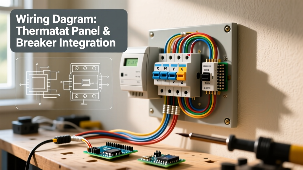
Below is the standard mapping for a 24VAC control circuit. Note that while wire colors are standardized by industry convention, previous installers may have used whatever wire was left in their van. Always verify continuity and voltage rather than trusting insulation colors.
| Terminal | Standard Color | Function & Panel Relationship | Voltage State (Active) |
|---|---|---|---|
| R / Rc / Rh | Red | 24VAC Hot from Transformer Secondary | 24VAC Constant |
| C | Blue/Black | 24VAC Common (Completes Circuit) | 0V (Reference) |
| W / W1 | White | Stage 1 Heat (Signals Furnace/Gas Valve) | 24VAC when calling |
| Y / Y1 | Yellow | Stage 1 Cool (Signals Outdoor Contactor) | 24VAC when calling |
| G | Green | Indoor Blower Fan Relay | 24VAC when calling |
| O / B | Orange | Heat Pump Reversing Valve | 24VAC (Cool/Heat dep.) |
Sizing the HVAC Branch Circuit Breaker: MCA vs. MOCP
When evaluating the high-voltage side of your thermostat's ecosystem, you must correctly size the breaker for the outdoor condenser. Amateurs often oversize breakers 'for safety,' which is a direct violation of NEC Article 440 (Air-Conditioning and Refrigerating Equipment) and creates a fire risk by allowing wires to melt before the breaker trips.
Look at the metal data plate on the outdoor condenser for two critical acronyms:
- MCA (Minimum Circuit Ampacity): This dictates your wire gauge. If the MCA is 18.5A, you must use wire rated for at least 18.5A. Because 12 AWG THHN/THWN-2 is rated for 20A, it meets the MCA. However, if the run is over 50 feet, upsizing to 10 AWG to mitigate voltage drop is recommended.
- MOCP (Maximum Overcurrent Protection): This dictates your breaker size. If the MOCP is 30A, you must install a 30-amp double-pole breaker (e.g., a Square D HOM230 or Siemens Q230), even if the MCA only requires 12 AWG wire. HVAC compressors have massive inrush currents (Locked Rotor Amps or LRA) that require time-delay or specific HACR-rated breakers to prevent nuisance tripping on startup.
Step-by-Step: Verifying Panel-to-Thermostat Continuity
When a thermostat is completely dead (blank screen), the issue is rarely the thermostat itself. It is almost always a failure in the high-voltage panel or the transformer. Follow this diagnostic sequence:
Step 1: Check the Main Panel Breakers
Locate the 120V breaker for the indoor air handler. Ensure it has not tripped to the center position. If it has tripped, you likely have a short in the blower motor capacitor or a grounded compressor wire. Do not simply reset it; investigate the short first.
Step 2: Inspect the 3-Amp Control Board Fuse
Turn off the 120V breaker at the panel. Open the indoor air handler access door (this depresses the safety door switch). Locate the main control board and find the 3A ATC (automotive-style) blade fuse. If a previous installer crossed the R and C wires at the thermostat, or if a 24V wire rubbed against a sharp copper refrigerant line and grounded out, this fuse will blow to protect the $400+ control board. Replace with an exact 3A equivalent.
Step 3: Test Transformer Output with a Multimeter
Restore power at the panel. Set your digital multimeter to VAC (Volts Alternating Current). Place your probes on the two secondary (low voltage) wires leaving the transformer. You should read between 24VAC and 28VAC. If you read 0VAC but have 120VAC on the primary side, the transformer's internal thermal overload has tripped or the winding is burned out. Replace the transformer.
Common Wiring Failures & Edge Cases
- The 'Phantom' C-Wire Issue: Many older homes wired for mechanical thermostats only pulled 4-conductor wire (Red, White, Yellow, Green). Modern smart thermostats require a continuous 24VAC power source via the C-wire. Attempting to 'power steal' from the heating relay can cause gas valves to chatter or micro-short cycles, degrading equipment lifespan. Pulling a new 18/5 or 18/8 shielded thermostat cable from the air handler to the wall plate is the only code-compliant, reliable fix.
- Heat Pump Reversing Valve Confusion (O vs. B): If your thermostat calls for cooling but blows hot air, the panel wiring is likely fine, but the thermostat configuration is wrong. Rheem and Ruud units typically energize the reversing valve on the B terminal (during heating), while Trane, Carrier, and Lennox energize it on the O terminal (during cooling). Check the manufacturer schematic before altering panel wiring.
- Undersized Disconnects: The NEC requires a disconnect switch within sight of the outdoor condenser. Ensure the pull-out disconnect box (e.g., Eaton DP60) is rated for the MOCP and that the internal fuses (if equipped) match the data plate requirements. A corroded disconnect block will cause voltage drop, leading to contactor chatter and burnt compressor terminals.
Code Compliance and Energy Efficiency Standards
When modifying the wiring diagram for home thermostat setups to accommodate modern smart home ecosystems, always adhere to local adaptations of the National Electrical Code (NEC). Furthermore, proper wiring and breaker sizing directly impact system efficiency. According to the EPA's ENERGY STAR program, properly wired and configured smart thermostats can save an average of 8% on heating and cooling bills, but only if the C-wire provides stable voltage to maintain Wi-Fi connectivity without backfeeding through relays.
Additionally, the U.S. Department of Energy emphasizes that ensuring your HVAC branch circuits and transformers are correctly sized prevents parasitic energy losses and voltage sag, which forces compressor motors to draw higher amperage and run hotter. By mastering the complete circuit—from the main panel breaker down to the 24V thermostat terminal—you ensure both the safety of your home's electrical infrastructure and the longevity of your climate control equipment.