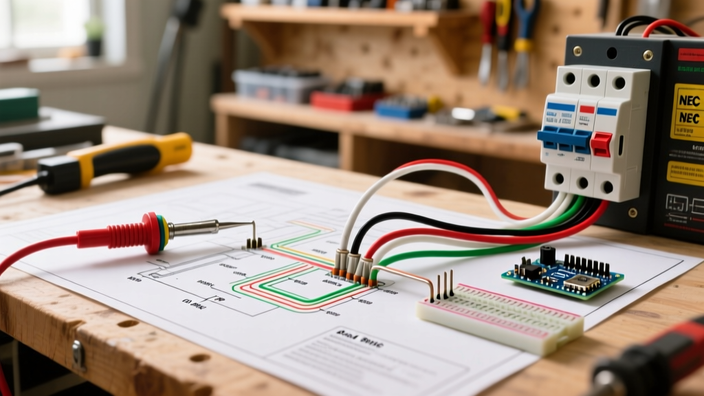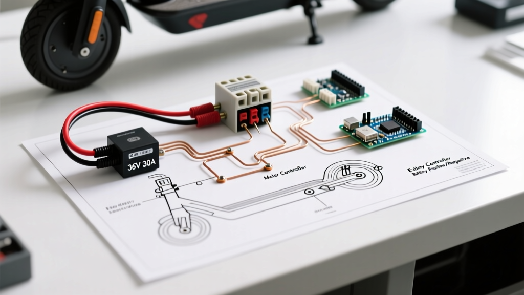

Designing a Safe 36V Scooter Power Distribution Panel
Whether you refer to it as a 36V or 36 volt electric scooter wiring diagram, the principles of DC power distribution remain identical. In the custom electric mobility space, moving away from basic inline automotive fuses toward a centralized Power Distribution Panel (PDP) with dedicated DC-rated circuit breakers is the hallmark of a professional build. A standard 10S lithium-ion scooter pack operates at 36V nominal, but peaks at 42V when fully charged and can deliver sustained currents of 25A to 40A, with transient spikes exceeding 60A during hard acceleration.
As of 2026, high-performance hub motors and mid-drive systems demand rigorous overcurrent protection. Using an AC-rated breaker in a 36V DC circuit is a critical safety hazard due to the absence of a zero-crossing voltage point, which prevents natural arc extinction. This guide breaks down the exact components, wire gauges, and step-by-step wiring flows required to build a robust breaker panel for your 36V electric scooter.
Core Components of the 36V Breaker Panel
Before routing a single wire, you must source components specifically rated for DC voltage and high continuous amperage. A complete 36V PDP requires the following hardware:
- Main DC Circuit Breaker: A 50A DC-rated breaker (e.g., Carling Technologies AM-Series or Bussmann 18X-Series). Expect to pay between $35 and $65 for genuine marine/industrial-grade DC breakers. Avoid cheap $10 unbranded automotive resets, which often weld internally under heavy inductive loads.
- Main Contactor (Solenoid): A heavy-duty relay like the Albright SW180-4 or a Curtis 36V 150A contactor. This handles the high-current switching to the motor controller, keeping heavy sparks away from your ignition switch.
- Precharge Resistor: A 150Ω 10W ceramic resistor. This is non-negotiable for protecting your contactor and the motor controller's input capacitors from inrush current.
- High-Current Connectors: Amass XT90-S (anti-spark) for the main battery lead, and 8 AWG silicone stranded wire (rated for 105°C) for the panel bus.
Safety Warning: DC arcs can reach temperatures exceeding 10,000°F and will melt standard plastic enclosures. Always use DC-specific breakers with internal arc chutes. For a deeper understanding of DC arc suppression physics, refer to Electronic Design's technical breakdown on DC circuit protection.
Step-by-Step 36V Wiring Flow
Follow this exact sequence to wire your power distribution panel. This flow ensures that the Battery Management System (BMS) and the main contactor are properly isolated and protected.
Step 1: Battery to Main Breaker
Connect the main positive lead (B+) from your 10S battery pack to the XT90-S anti-spark connector. From the connector, route 8 AWG silicone wire directly to the Line terminal of your 50A DC circuit breaker. The BMS should be wired in-line on the negative (B-) lead, acting as your primary over-discharge and short-circuit protection. For more on configuring 10S battery packs safely, consult Battery University's guide on serial and parallel configurations.
Step 2: Breaker to Contactor and Precharge
Run a short, heavy-gauge jumper from the Load terminal of the DC breaker to the main high-current terminal of the contactor. Crucial Step: Solder your 150Ω precharge resistor across the two main high-current terminals of the contactor. When the ignition switch energizes the contactor coil, the resistor allows a tiny trickle of current to safely charge the motor controller's capacitors before the main contacts close, preventing a massive spark that could weld the contactor shut.
Step 3: Contactor to Motor Controller
Route the output of the contactor directly to the main positive input (P+) of your motor controller. Ensure all high-current connections are crimped with closed-end copper ring terminals and heat-shrunk. Do not rely on solder alone for high-current mechanical joints, as solder can creep and loosen under vibration.
Step 4: Auxiliary Panel and Ignition
Tap into the Line side of the main breaker (or use a secondary 10A DC breaker) to power your auxiliary bus. This bus feeds your DC-DC step-down converter (36V to 12V for lights and horn), your ignition switch, and the low-current coil trigger for the main contactor. Use 14 AWG wire for the auxiliary bus and protect it with a 15A automotive blade fuse panel.
Wire Gauge and DC Breaker Sizing Matrix
Undersizing your wire or breaker in a 36V system leads to severe voltage drop, which starves your motor controller and causes premature BMS shutdowns. Use the matrix below to size your panel components correctly based on your motor controller's continuous amperage rating.
| Controller Continuous Amps | Minimum Wire Gauge (AWG) | Recommended DC Breaker Size | Typical Application |
|---|---|---|---|
| 15A - 20A | 12 AWG Silicone | 30A DC Breaker | Commuter / Light Duty Scooters |
| 22A - 30A | 10 AWG Silicone | 40A DC Breaker | Standard 36V 500W Hub Motors |
| 32A - 40A | 8 AWG Silicone | 50A DC Breaker | High-Performance / Dual Motor |
| 45A - 60A | 6 AWG Silicone | 70A DC Breaker | Off-Road / Mid-Drive Conversions |
Note: Ampacity ratings assume standard 105°C silicone jacketed wire in free air. If routing wires through enclosed scooter decks with poor ventilation, step up one AWG size to compensate for thermal derating.
Critical Failure Modes in 36V DC Panels
Even with a perfect wiring diagram, real-world conditions introduce edge cases that can destroy your electrical system. Understanding these failure modes is what separates DIY hobbyists from professional EV technicians.
1. Contactor Welding from Missing Precharge
The Failure: You turn the key, hear a loud 'pop', and the scooter takes off even when the key is turned off. The main contactor has welded itself in the closed position.
The Cause: Motor controllers use large electrolytic capacitor banks. When 42V hits empty capacitors, they act as a dead short, drawing hundreds of amps for a fraction of a millisecond. This inrush current arcs across the contactor points, melting them together.
The Fix: Always install a precharge resistor, or use a smart precharge board that monitors capacitor voltage before closing the main relay.
2. AC Breaker Catastrophic Arcing
The Failure: The main breaker trips during a hard hill climb, but the internal contacts melt, and the breaker catches fire.
The Cause: Standard AC breakers rely on the AC sine wave crossing zero volts 120 times a second to extinguish the internal arc when the contacts separate. In a 36V/42V DC circuit, there is no zero-crossing. The arc sustains, generating massive heat.
The Fix: Only use breakers explicitly stamped with a DC voltage rating (e.g., '48VDC' or 'Max 65VDC'). Verify the internal arc chute design by checking manufacturer datasheets, such as those provided by Littelfuse for DC circuit protection.
3. Voltage Drop Across Cheap Bus Bars
The Failure: The scooter cuts out under heavy load, and the BMS logs an over-current fault, even though the motor is drawing within limits.
The Cause: Cheap brass or nickel-plated steel bus bars on generic fuse panels introduce high resistance. A 0.05-ohm resistance across a poor connection at 40A results in a 2V drop and 80W of heat dissipated directly inside your battery enclosure.
The Fix: Use pure copper, tin-plated bus bars. Sand the contact surfaces lightly before crimping to remove oxidation, and apply a dielectric grease to prevent future corrosion.
Final Assembly and Testing Protocol
Once your 36V electric scooter wiring diagram is physically realized, do not immediately connect the main battery. Perform a continuity check with a multimeter to ensure the main positive and negative buses are not shorted. Next, connect the battery and use your multimeter to verify 42V at the input of the motor controller before triggering the contactor. Finally, engage the ignition. You should hear a soft 'click' from the contactor with zero visible sparking at the XT90 connector. If sparking occurs, your precharge circuit is faulty and must be addressed before riding.