
Core Electrical Architecture of Cub Cadet Tractors
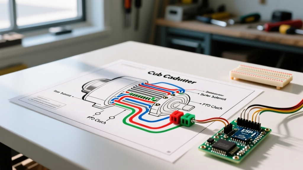
Understanding the 12-volt DC electrical system in modern lawn tractors requires more than just tracing colored wires; it demands a systematic approach to motor circuits, safety interlocks, and charging systems. Whether you are servicing a classic LT1045 or a modern XT2 Enduro Series, interpreting the wiring diagram for a Cub Cadet is the first step toward accurate diagnostics. In this motor wiring tutorial, we break down the starter motor circuit, the Power Take-Off (PTO) clutch motor, and the critical safety interlock logic that governs them.
As of 2026, newer Electronic Fuel Injection (EFI) models, such as those equipped with the Kohler 7000 Series EFI engines, have introduced additional ECU power relays into the traditional MTD/Cub Cadet wiring harness. This means the starter motor circuit is now intertwined with low-amperage ECU wake-up signals, making precise schematic reading more important than ever.
Decoding the Starter Motor and Solenoid Circuit
The starter motor on a Cub Cadet tractor typically draws between 80 and 150 amps under load, depending on the engine displacement and compression ratio. Because the ignition switch cannot handle this amperage, a heavy-duty starter solenoid acts as a relay. When consulting the factory schematic, you will generally encounter one of two solenoid configurations.
3-Terminal vs. 4-Terminal Solenoid Configurations
| Feature | 3-Terminal Solenoid | 4-Terminal Solenoid |
|---|---|---|
| Large Terminals | Battery In (B+), Starter Out (M) | Battery In (B+), Starter Out (M) |
| Small Terminals | Trigger (S), Grounds via mounting bracket | Trigger (S), Dedicated Ground (G) |
| Common Applications | Older LT series, basic Kawasaki/Kohler setups | Modern XT1/XT2, EFI models, complex interlocks |
| Installation Note | Mounting surface MUST be bare metal (no paint) | Can be mounted anywhere; ground wire completes circuit |
Pro-Tip for 4-Terminal Diagnostics: If you turn the key to the 'START' position and hear a faint click but the starter motor does not engage, use a multimeter to check for 12V at the 'S' terminal. If 12V is present, check the 'G' terminal for continuity to the chassis. A broken ground wire or a corroded safety switch (like the brake pedal switch) will prevent the solenoid coil from energizing.
PTO Clutch Motor Wiring and Air Gap Calibration
The electric PTO clutch is essentially an electromagnetic motor that engages the mower deck blades. Most Cub Cadet tractors utilize clutches manufactured by Ogura or Warner Electric. These are 12V DC electromagnetic coils that typically draw 2.5 to 4.0 amps.
Electrical Specifications and Failure Modes
- Operating Voltage: 12V DC (Minimum 11.5V required for reliable engagement)
- Coil Resistance: Typically 3.0 to 5.0 ohms at room temperature
- Wire Gauge: 12 AWG recommended for the feed line to minimize voltage drop over the distance to the front of the deck
Expert Insight: The most common cause of PTO clutch electrical failure is not a burnt coil, but an improper air gap. If the gap between the armature and the rotor exceeds 0.020 inches, the magnetic field cannot fully pull the plate in. This causes 'slipping,' which generates immense heat, eventually melting the coil's internal windings and creating an open circuit. Always check the air gap with a feeler gauge and adjust it to the manufacturer's specification of 0.010 to 0.015 inches using the adjustment nuts located around the clutch perimeter.
Safety Interlock Logic: The Hidden Motor Killers
Modern Cub Cadet wiring diagrams feature a complex safety interlock module (often a small black box with a multi-pin connector) or a series of normally open (NO) and normally closed (NC) switches wired in series. These switches protect the operator but frequently cause 'no-crank' or 'engine dies when PTO engaged' complaints.
The Interlock Sequence
- Brake Pedal Switch: Must be depressed (circuit closed) to allow the starter solenoid to receive a ground path.
- Seat Switch: Normally closed when occupied. If the operator leaves the seat while the PTO is engaged, the module instantly cuts the ground path to the PTO clutch relay and the ignition module.
- PTO Engagement Switch: Must be in the 'OFF' (disengaged) position during engine cranking. If the PTO is engaged, the interlock prevents the starter motor from receiving the 12V trigger signal.
Wire Gauge Selection and Routing Standards
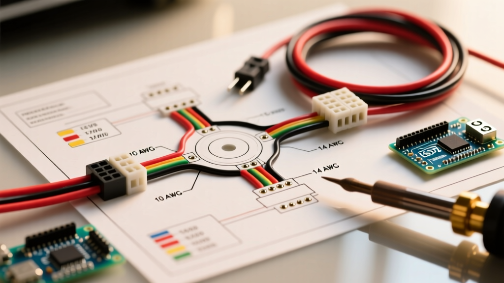
When repairing or extending wires on a Cub Cadet tractor, adhering to proper ampacity standards is critical to prevent voltage drop and potential electrical fires. While the NFPA 70 National Electrical Code primarily governs AC building wiring, its DC ampacity tables for copper wire are the industry standard for automotive and small engine applications.
| Application | Recommended AWG | Max Amperage | Insulation Type |
|---|---|---|---|
| Battery to Solenoid / Starter | 10 AWG or 8 AWG | 150A+ (Surge) | Stranded Copper, PVC/XLPE |
| Alternator/Regulator to Battery | 12 AWG | 30A - 40A | Stranded Copper, High-Temp |
| PTO Clutch Feed | 12 AWG | 15A | Stranded Copper, Abrasion-resistant |
| Ignition Switch / Safety Switches | 16 AWG or 18 AWG | 5A - 10A | Stranded Copper, Standard PVC |
Troubleshooting Common Motor Wiring Failures
Before replacing a starter motor or PTO clutch, always perform a Voltage Drop Test. This is the single most effective diagnostic tool for 12V DC tractor circuits.
How to Perform a Starter Circuit Voltage Drop Test
- Set your digital multimeter to DC Volts.
- Place the red probe directly on the battery's positive post (not the clamp, the actual lead post).
- Place the black probe on the starter motor's B+ terminal (the large post where the heavy cable connects to the motor).
- Have an assistant turn the ignition key to 'START' and hold it while the engine cranks (or attempts to crank).
- Interpretation: A healthy circuit will show a voltage drop of less than 0.5V. If your meter reads 2.0V or higher, you have severe resistance in the cable, a corroded battery terminal, or a failing internal solenoid contact. Do not replace the starter motor until the cable resistance is eliminated.
2026 EFI ECU Power Relay Considerations
If you are working on a late-model Cub Cadet with an EFI engine, the wiring diagram will show an ECU main relay. This relay is triggered by the ignition switch but is often gated by the same safety interlock module that controls the starter. If the ECU does not receive 12V within 500 milliseconds of the key turning to the 'ON' position, the fuel pump will not prime, and the starter motor will crank an engine that refuses to fire. Always verify ECU pin 1 (Main Power) and Pin 4 (Ground) for a solid 12V reference before condemning the fuel system or ignition coils.
Frequently Asked Questions
Where can I find the exact schematic for my specific Cub Cadet model?
The most reliable method is to locate your model and serial number tag (usually under the seat or on the rear frame) and search the Cub Cadet Official Manual Repository. Alternatively, the Jack's Small Engines Parts & Schematics Database provides excellent exploded views and wiring diagrams for older MTD-manufactured models.
Why does my Cub Cadet starter motor spin but not engage the flywheel?
This is rarely a wiring issue and almost always a mechanical failure of the starter's Bendix drive or a weak solenoid pull-in coil. However, if the battery voltage drops below 9.5V during cranking, the solenoid may not have enough electromagnetic force to fully throw the Bendix gear into the flywheel ring gear. Perform a load test on the battery first.
Can I bypass the safety interlock switches to test the starter?
While you can temporarily jump the solenoid's 'S' terminal to the 'B+' terminal with a heavy-gauge jumper wire to test the starter motor itself, never bypass the seat or brake safety switches for normal operation. Bypassing these switches removes critical operator protections and poses a severe laceration or run-over hazard.