
Strategic Planning for Leeson Motor Installations
Leeson Electric, now a premier brand under the Regal Rexnord umbrella, remains a dominant force in industrial, agricultural, and commercial HVAC applications. As of 2026, a standard 1.5 HP Leeson General Purpose motor (such as the C145T17FB50C) typically retails between $280 and $340. Given this investment, improper wiring is not just a safety hazard; it is a direct path to catastrophic winding failure. Understanding how to read and execute a wiring diagram for Leeson electric motors is the most critical step in your installation planning guide.
This guide moves beyond basic plug-and-play assumptions. We will decode NEMA-standard lead markings, calculate precise conductor sizing per the latest National Electrical Code (NEC), and outline the exact pre-energization protocols required to ensure your motor operates at peak efficiency for its entire lifecycle.
⚠️ Critical Safety & Compliance Notice:All motor installations must comply with NFPA 70 (National Electrical Code), specifically Article 430. Always verify local jurisdiction adoptions of the 2023/2026 NEC revisions before terminating conductors. Lockout/Tagout (LOTO) procedures must be strictly enforced during the planning and termination phases.
Decoding the Leeson Nameplate: Your Primary Blueprint
Before you even open the conduit box to look at the internal schematic, the motor nameplate provides the foundational data required for your installation plan. Leeson nameplates are densely packed with critical metrics. Here is what you must extract for your wiring plan:
- Volts (V): Dual voltage motors will list two values (e.g., 115/230V or 230/460V). Your supply voltage must match one of these exactly. Operating a 230V motor on 208V will cause a 20% drop in starting torque and severe overheating.
- Full Load Amps (FLA): This is the baseline for sizing your conductors and overload relays. For a 115/230V motor, the FLA will also be dual-listed (e.g., 20.0/10.0A).
- Service Factor (SF): A 1.15 SF means the motor can handle a 15% overload continuously under specific conditions, but your wiring and breaker must still be sized based on the standard FLA, not the SF-adjusted amperage.
- Code Letter: Indicates the locked-rotor kVA per horsepower, which is essential for calculating voltage drop during startup and sizing instantaneous trip breakers.
Core Wiring Diagram Configurations
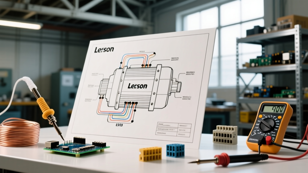
Leeson motors adhere to the NEMA MG 1 standard for lead numbering and color coding. The physical wiring diagram is almost always printed on the inside of the terminal (conduit) box cover. Below are the structural frameworks for the two most common Leeson configurations.
1. Single-Phase Dual Voltage (115/230V) - e.g., C145T Series
Single-phase Leeson motors typically feature capacitor-start designs with centrifugal switches. They utilize numbered leads (T1 through T8) and sometimes color-coded wires for the thermal protector. The fundamental rule for dual-voltage single-phase motors is that the run windings are reconfigured in series for high voltage and in parallel for low voltage, while the start winding remains connected to the 115V tap internally.
| Voltage Configuration | Line Connections (L1, L2) | Internal Lead Ties (Wire Nuts) | Rotation Reversal |
|---|---|---|---|
| High Voltage (230V) | L1 to T1 & T4 L2 to T5 & T8 |
Tie T2 to T3 and T6 to T7 | Swap T5 and T8 (Start Winding) |
| Low Voltage (115V) | L1 to T1, T3, T6 L2 to T2, T4, T5, T7, T8 |
None (All tied to Line) | Swap T5 and T8 (Start Winding) |
2. Three-Phase Dual Voltage (230/460V) - e.g., C6T Series
Three-phase Leeson motors (typically 9-lead Wye/Star connected for standard 230/460V applications) are significantly easier to wire because they lack centrifugal switches and start capacitors. The stator windings are simply reconfigured from a series-Wye (high voltage) to a parallel-Wye (low voltage).
| Voltage Configuration | Line Connections (L1, L2, L3) | Internal Lead Ties (Wye Point) |
|---|---|---|
| High Voltage (460V) | L1 to T1 & T7 L2 to T2 & T8 L3 to T3 & T9 |
Tie T4, T5, and T6 together and insulate |
| Low Voltage (230V) | L1 to T1 & T7 L2 to T2 & T8 L3 to T3 & T9 |
Tie T4-T7, T5-T8, T6-T9 to respective lines |
Note: Always verify the internal diagram. Some specialized Leeson HVAC motors use Delta configurations, which utilize a completely different T1-T9 mapping.
Sizing Conductors and Overload Protection (NEC Article 430)
A common failure mode in 2026 installations is sizing the circuit breaker to the motor's FLA rather than following NEC motor circuit rules. Motors require high inrush current (up to 600% of FLA) to start. If you use a standard thermal breaker sized to the FLA, it will trip instantly upon startup.
According to NEC Article 430.22, branch circuit conductors must be sized at 125% of the motor's full-load current. Overload protection (usually built into the motor starter or VFD) is sized between 115% and 125% of the FLA. Short-circuit and ground-fault protection (the breaker) is sized much higher, per NEC Table 430.52.
Wire Gauge & Breaker Sizing Matrix (Common Leeson Ratings)
| Motor HP | Voltage / Phase | Nameplate FLA | Min Conductor Ampacity (125%) | Recommended THHN Wire Size | Max Inverse Time Breaker |
|---|---|---|---|---|---|
| 1.0 HP | 115V / 1-Phase | 16.0A | 20.0A | 12 AWG | 40A |
| 1.5 HP | 230V / 1-Phase | 10.0A | 12.5A | 14 AWG (12 AWG rec.) | 25A |
| 3.0 HP | 230V / 3-Phase | 9.6A | 12.0A | 14 AWG (12 AWG rec.) | 25A |
| 5.0 HP | 460V / 3-Phase | 7.6A | 9.5A | 14 AWG | 20A |
Common Installation Failure Modes & Troubleshooting
Even with the correct wiring diagram for Leeson electric motors, physical installation errors cause the majority of premature failures. Based on industry motor troubleshooting data from Fluke, here are the edge cases you must plan for:
- High-Resistance Terminations: Leeson terminal blocks require specific torque values. A loose spade connector on a T1 lead will arc, generating localized heat that degrades the winding insulation, leading to a phase-to-ground fault. Always use a calibrated torque screwdriver (typically 12-15 in-lbs for standard 10-32 terminal screws).
- Incorrect Voltage Tap Selection: Wiring a 230/460V motor for 230V but supplying it with 460V will not just trip the breaker; it will instantly vaporize the start windings and potentially cause the terminal block to melt. Always double-check the physical wire nut connections against the supply voltage before closing the conduit box.
- Thermal Protector Bypass: Some Leeson single-phase motors feature an internal thermal protector with two yellow or white leads. Installers sometimes mistakenly tie these into the power circuit. These leads must be wired in series with the motor contactor coil circuit, not the main power lines.
Step-by-Step Pre-Energization Checklist
Before throwing the disconnect switch, run through this mandatory verification protocol:
- Step 1: Megger Testing. Use an insulation resistance tester (Megger) at 500V DC to test phase-to-ground and phase-to-phase. Readings should be >10 Megohms for a new Leeson motor. Anything below 2 Megohms indicates moisture ingress or shipping damage.
- Step 2: Rotation Check (Unloaded). For 3-phase motors, bump the starter for a fraction of a second to verify rotation direction before coupling the motor to the load. Reversing rotation under load can destroy driven equipment.
- Step 3: Voltage Balance. Measure the supply voltage at the motor terminal block while running. A voltage unbalance of just 1% between phases can cause a 6% to 10% temperature rise in the motor windings. If unbalance exceeds 1%, investigate the utility supply or VFD output.
- Step 4: Amp Draw Verification. Use a true-RMS clamp meter to measure the current on all legs. Compare against the nameplate FLA. If the motor is drawing 10% over FLA while unloaded, the mechanical alignment is binding, or the voltage tap is incorrect.
Expert Insight: When planning the conduit run for a Leeson motor, always account for voltage drop. If the run exceeds 100 feet, bump the wire gauge up by one size from the NEC minimum. A 3% voltage drop at the motor terminals during startup can result in a 9% loss of starting torque, causing the motor to stall and trip the overloads.
By treating the wiring diagram for Leeson electric motors as a comprehensive system blueprint rather than a simple connection map, you ensure reliable, code-compliant, and long-lasting operation. Proper planning, precise termination, and adherence to NEC Article 430 will protect your equipment and your facility's electrical infrastructure.