
Why High-CFM Electric Fans Require a Relay Contactor
When upgrading a workshop, attic, or commercial kitchen with a high-capacity ventilation system, direct-switching the motor is a critical mistake. High-CFM exhaust fans—such as the Broan 504 or Panasonic WhisperCeiling high-capacity models—utilize heavy induction motors. While their running amperage might seem manageable, their startup surge is destructive to standard wall switches and mechanical thermostats.
This is where mastering electric fan wiring with relay components becomes essential. By using a heavy-duty relay (often referred to as a contactor in AC motor applications), you isolate the high-amperage load circuit from the low-amperage control circuit. This prevents contact arcing, extends the lifespan of your thermostat by decades, and ensures compliance with the National Electrical Code (NEC) regarding motor disconnects.
The Thermostat Switch Bottleneck and Inductive Kickback
A standard line-voltage thermostat, like the Honeywell T410A, is rated for 22 Amps resistive loads. However, induction motors present a highly inductive load. When the thermostat opens to turn off the fan, the collapsing magnetic field in the motor and relay coil generates a high-voltage inductive kickback (back-EMF). Over time, this causes pitting and micro-welding on the thermostat's internal contacts. By introducing an Omron or Eaton relay into the circuit, the thermostat only switches the relay's coil (which draws less than 0.2 Amps), completely eliminating the arcing bottleneck.
Component Selection: Sizing Your Relay and Wire Gauge
Selecting the correct relay and wire gauge is dictated by the motor's Full Load Amps (FLA) and Locked Rotor Amps (LRA). For a typical 120V AC high-CFM exhaust fan drawing 8A FLA, the LRA can spike to 35A for a fraction of a second during startup. You must size your relay to handle the inductive surge without contact welding.
| Component | Recommended Model (2026) | Specifications | Avg. Cost |
|---|---|---|---|
| Heavy-Duty Relay | Omron G7L-2A-BUB (120VAC) | 25A DPST-NO, Quick Connect | $14.50 |
| Control Switch | Honeywell T410A1018 | Line Voltage, 22A Resistive | $28.00 |
| Load Wire (15-20A) | Southwire THHN 12 AWG | 600V, Stranded Copper | $0.48/ft |
| Snubber Circuit | Okaya SUPX4915 | RC Snubber, 0.15uF + 100 Ohm | $6.25 |
| Enclosure | Bud Industries NBF-3206 | NEMA 4X IP66 Polycarbonate | $32.00 |
Step-by-Step 120V AC Electric Fan Wiring With Relay
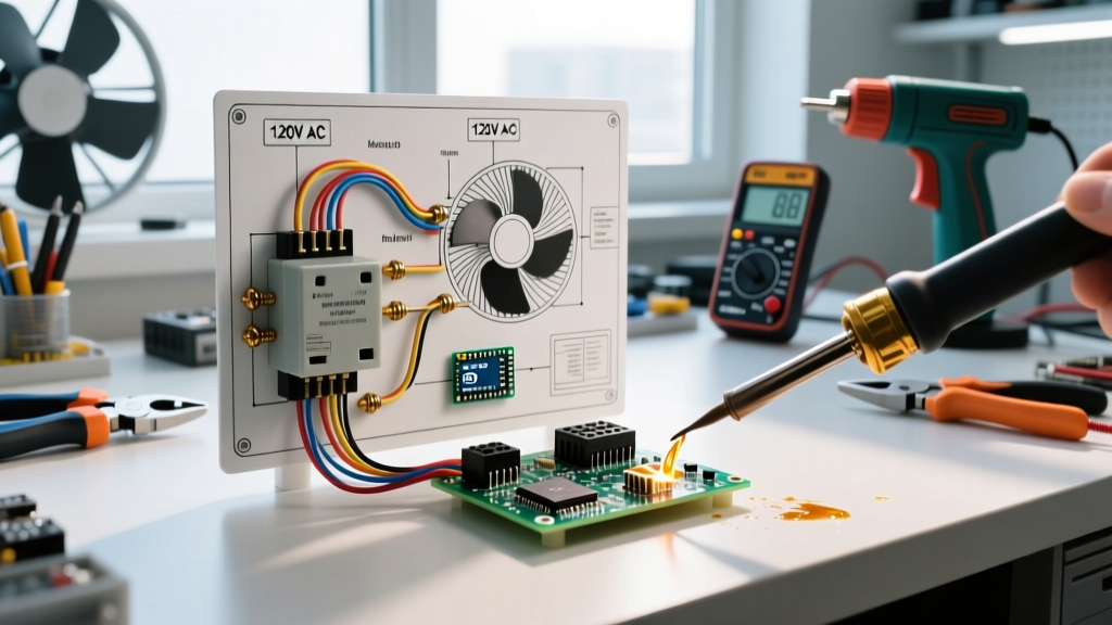
The following procedure outlines wiring a 120V AC exhaust fan using a dedicated 20A branch circuit and a 120V AC coil relay. Always verify local codes and consult the NFPA NEC guidelines before beginning.
Phase 1: Preparation and Safety Lockout
- De-energize the Circuit: Turn off the 20A double-pole or single-pole breaker at the main panel. Apply a Lockout/Tagout (LOTO) device to comply with OSHA electrical safety standards.
- Verify Zero Voltage: Use a CAT III-rated multimeter (e.g., Fluke 117) to test Line-to-Neutral and Line-to-Ground. Confirm 0.0V before touching any conductors.
- Mount the Enclosure: Secure the NEMA-rated enclosure near the fan motor, ensuring you have at least 3 feet of clearance for maintenance as required by NEC 110.26.
Phase 2: Wiring the Load Circuit (High Amperage)
- Route 12 AWG THHN wire from the 20A breaker panel to the relay enclosure. Connect the incoming Hot (Black) wire to the relay's L1 (Line) terminal.
- Connect the outgoing Hot wire leading to the fan motor to the relay's T1 (Load) terminal. Use a crimped spade connector and torque to the manufacturer's specification (usually 12-15 in-lbs) to prevent hot spots.
- Wire the Neutral (White) directly from the panel to the fan motor using a Wago 221 lever nut inside the enclosure. The neutral does not pass through a single-pole DPST relay.
- Connect the bare copper or green Equipment Grounding Conductor (EGC) to the enclosure's grounding bus bar and pigtail to the fan motor chassis.
Phase 3: Wiring the Control Circuit (Low Amperage)
- Run 18 AWG or 16 AWG control wire from the remote thermostat location into the relay enclosure.
- Connect the incoming 120V Hot wire to one side of the Honeywell thermostat. Run the switched Hot from the thermostat to the relay coil terminal A1.
- Connect the Neutral wire directly from the panel (or the load neutral bus) to the relay coil terminal A2.
- Critical E-E-A-T Step - Coil Suppression: Wire an RC snubber (like the Okaya SUPX4915) in parallel with the A1 and A2 coil terminals. As detailed by experts at Electrical Technology, this absorbs the inductive voltage spike when the thermostat opens, preventing the thermostat contacts from degrading over time.
Troubleshooting Common Relay Failure Modes
Even with proper installation, relays in high-vibration or high-heat appliance environments can fail. Recognizing these specific failure modes will save you hours of diagnostic time.
- Contact Welding (Fan Won't Turn Off): If the fan runs continuously even when the thermostat calls for cooling, the relay's internal contacts have likely micro-welded together due to LRA startup arcing. Fix: Replace the relay with a higher amperage rating or add a soft-start module to the motor.
- Coil Burnout (Fan Won't Turn On): Characterized by a distinct burnt plastic or ozone smell near the enclosure. This occurs if the coil voltage drops below 85% of its nominal rating, causing the armature to chatter and overheat the coil windings. Fix: Check for voltage drop on the 18 AWG control wires; upgrade to 14 AWG if the thermostat is more than 50 feet away.
- Armature Chattering (Loud Humming): A loud 60Hz hum indicates the relay's magnetic armature is not seating fully. This is usually caused by dust, rust, or insect debris on the mating surfaces of the relay's magnetic core. Fix: Replace the relay; do not attempt to lubricate the magnetic faces, as this will attract more debris.
Expert Insight: Never use a DC-rated automotive relay (like a standard 40A Bosch-style cube relay) for a 120V AC appliance motor. AC arcs are self-extinguishing at the zero-crossing of the sine wave, whereas DC arcs are continuous. Using a DC relay on an AC motor circuit will result in catastrophic contact failure and a severe fire hazard.
Safety and NEC Compliance for Appliance Motors
When wiring any appliance motor, adherence to NEC Article 430 is non-negotiable. Section 430.52 dictates the maximum size of the overcurrent protective device (breaker). For a standard AC motor, the breaker can be sized up to 250% of the motor's FLA to accommodate the startup surge without nuisance tripping.
However, the wire gauge must still be protected according to NEC 240.4. If you have a 10A FLA motor and use a 25A breaker to handle the startup surge, you must use 10 AWG wire (rated for 30A), not 14 AWG wire. The relay acts as the switching mechanism, but the branch circuit breaker and wire gauge must be perfectly harmonized to prevent the wire insulation from melting during a locked-rotor fault condition.
Final Testing Protocol
Once all connections are torqued and the enclosure cover is secured, remove the LOTO device and restore power. Use a clamp meter (e.g., Fluke 376) around the single Hot load wire to measure the startup inrush current and the steady-state running current. Verify that the running current is within 10% of the motor's nameplate FLA. Finally, adjust the thermostat to trigger the relay, listening for a crisp, singular "clack" sound, indicating a healthy, chatter-free armature engagement.