
Decoding the '5-Way' Terminology: What Are You Actually Wiring?
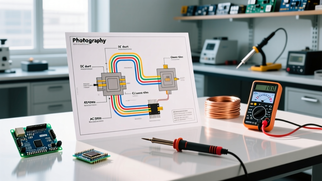
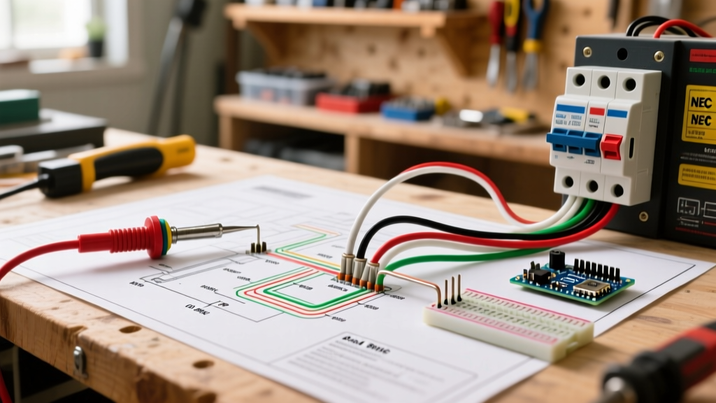
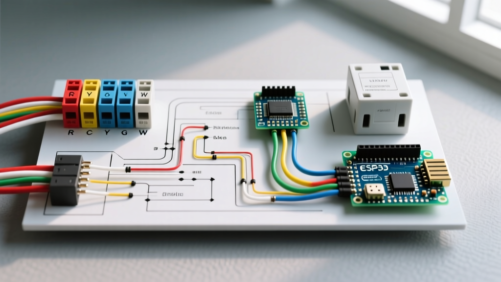
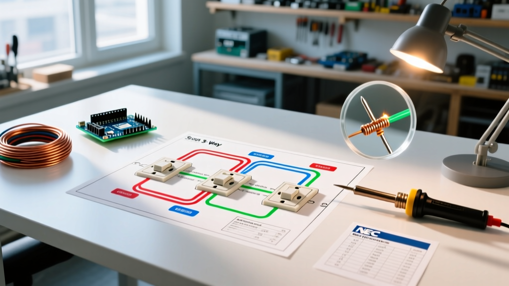
When DIYers and professional electricians search for a wiring diagram for 5 way switch configurations, they are usually confronting a terminology collision. In standard US residential electrical systems governed by the National Electrical Code (NEC), there is no physical '5-way' wall switch. Standard multi-location switching relies on Single-Pole, 3-Way (SPDT), and 4-Way (DPDT) switches. To control a single light fixture from five distinct locations, you must daisy-chain two 3-way switches and three 4-way switches.
Conversely, in appliance repair, ceiling fan installations, and electronics, a '5-way switch' refers to a 5-position rotary selector switch (such as a 5-speed fan switch or a guitar pickup selector). This 2026 installation planning guide breaks down the exact wiring topology, NEC box-fill requirements, and component selection for both scenarios, ensuring your project passes inspection and functions flawlessly.
Scenario A: Planning a 5-Location Residential Lighting Circuit
Controlling a hallway, large stairwell, or multi-entry garage from five different doors requires a precise sequence of switches. The fundamental rule of multi-way wiring is that 3-way switches must always bookend the circuit, with 4-way switches placed in the middle.
Circuit Topology & Cable Routing
For a standard 120V, 15-Amp lighting circuit, you will use 14/3 NM-B (Romex) cable, or 12/3 NM-B if the circuit is on a 20-Amp breaker. As of 2026, 12/3 NM-B averages around $0.85 per foot, so precise measurement is critical to avoid budget overruns.
- Location 1 (Line/Power Source): 3-Way Switch. Power enters the common terminal. Travelers exit to Location 2.
- Location 2: 4-Way Switch. Travelers from Location 1 enter one set of brass screws; travelers to Location 3 exit the black screws.
- Location 3: 4-Way Switch. Acts as a pass-through bridge.
- Location 4: 4-Way Switch. Final bridge before the load.
- Location 5 (Load/Light Fixture): 3-Way Switch. Travelers enter, and the common terminal feeds the switched hot to the light fixture.
NEC Box Fill Calculations (The Planning Bottleneck)
The most common reason multi-switch installations fail inspection is violating NEC Article 314.16 regarding box fill capacity. A 4-way switch has four terminal screws (excluding ground), meaning it counts as four conductor volumes inside the junction box. According to the NFPA NEC Guidelines, you must calculate the cubic inch requirements before purchasing electrical boxes.
| Component in 4-Way Box | 14 AWG Volume (2.0 cu in each) | 12 AWG Volume (2.25 cu in each) |
|---|---|---|
| 4-Way Switch (4 volumes) | 8.0 cu in | 9.0 cu in |
| Ground Wires (1 volume total) | 2.0 cu in | 2.25 cu in |
| Clamps (1 volume total, if internal) | 2.0 cu in | 2.25 cu in |
| Current-Carrying Wires (e.g., 6 wires) | 12.0 cu in | 13.5 cu in |
| Total Minimum Box Size | 24.0 cu in | 27.0 cu in |
Pro Tip: Always use deep 2.5-inch or 3-inch single-gang 'old work' boxes for 4-way switches to comfortably accommodate the stiff 12/3 or 14/3 traveler wires.
Scenario B: The Smart Switch Alternative (Avoiding 14/3 NM-B)
Pulling three-conductor cable through finished walls across five locations is a drywall-destroying nightmare. In 2026, the industry standard for retrofitting 5-location circuits is using smart switches with wireless companions. This entirely eliminates the need for traveler wires.
Lutron Caseta vs. Leviton Decora Smart
By installing a smart master switch at the line or load location, and pairing it with wireless Pico remotes or battery-powered companion switches at the other four locations, you bypass the physical 4-way wiring diagram entirely.
- Lutron Caseta (PD-5S-DV): Requires the Lutron Smart Bridge. Master switch costs ~$65; each Pico remote and wallplate adapter costs ~$25. Total 5-location cost: ~$165.
- Leviton Decora Smart (D26SR): Matter/Thread compatible, no hub required for basic setups. Master switch ~$45; wireless companions ~$20 each. Total 5-location cost: ~$125.
Code Warning: Even when using wireless companions, the physical wall boxes at locations 2, 3, and 4 must still contain a neutral wire (white) and a ground (bare/green) to comply with modern smart-home readiness codes, even if the wireless remote itself is battery-powered and simply covers a blank plate.
Scenario C: Planning a 5-Position Rotary Switch (Appliance & Fan)
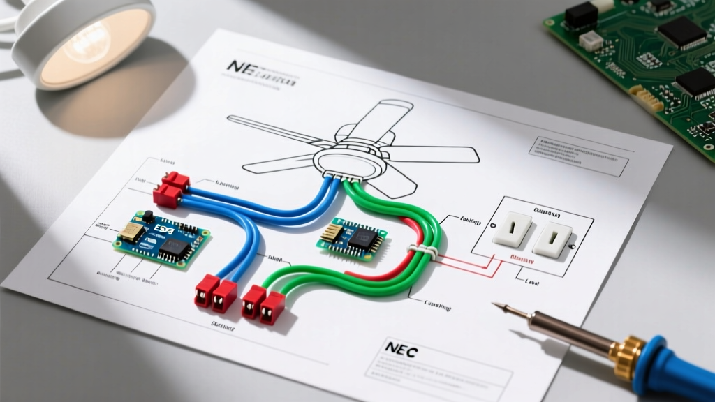
If your search for a wiring diagram for 5 way switch was intended for an appliance, you are likely dealing with a 5-position rotary switch. The most common residential application is a 5-speed ceiling fan switch (e.g., Hunter Part #9050 or a generic 5-wire selector).
Rotary Switch Pinout Logic
These switches typically feature one 'L' (Line/Hot) terminal and four numbered output terminals (1, 2, 3, 4), plus an 'Off' position.
- Position 1 (High Speed): Connects L to Terminal 1 (Direct hot to main motor winding).
- Position 2 (Medium-High): Connects L to Terminal 2 (Routes through first choke/inductor coil).
- Position 3 (Medium): Connects L to Terminal 3 (Routes through second coil tap).
- Position 4 (Low): Connects L to Terminal 4 (Routes through maximum resistance coil).
- Position 5 (Off): Breaks the circuit.
For electronics projects utilizing a 5-way, 4-deck rotary selector (like the Alpha or Lorlin brands used in audio crossovers), always map your continuity with a digital multimeter on the diode/beep setting before soldering. The physical detents do not always match the internal wafer rotation sequence.
Common Failure Modes & Troubleshooting
Whether you are wiring a 5-location wall circuit or a 5-way rotary appliance switch, these are the most frequent points of failure encountered in the field:
1. The 'Traveler Cross' in Wall Switches
Symptom: The light only works if Switch 1 is UP and Switch 3 is DOWN. If Switch 2 is toggled, the circuit dies entirely.
Cause: The traveler wires on one of the intermediate 4-way switches are crossed incorrectly. A 4-way switch has two distinct pairs of terminals (often colored brass and black). You must connect the incoming travelers to one color pair, and the outgoing travelers to the other color pair. Never mix an incoming and outgoing wire on the same color pair.
2. Induced Voltage on Long Traveler Runs
Symptom: LED bulbs flicker or glow faintly when turned off in a 5-location setup.
Cause: Running 14/3 cable over 75+ feet creates capacitive coupling between the parallel traveler wires, inducing a phantom voltage (often 30V-50V). Standard DOE wiring guidelines note that modern low-wattage LEDs are highly susceptible to this.
Fix: Install a 1-watt, 500-ohm wirewound bleeder resistor (like the Lutron LUT-MLC) across the load (hot and neutral) at the light fixture to dissipate the phantom voltage.
3. Rotary Switch Contact Arcing
Symptom: A 5-way fan switch melts or smells like burning ozone.
Cause: Using a switch rated for 1.5A on a motor with a high startup inrush current. Always ensure your rotary switch is rated for inductive loads (L-Rating), not just resistive loads. A standard 5A resistive switch may fail at 1.5A inductive.
Final Planning Checklist
Before cutting any drywall or stripping any wire, verify your installation plan against this checklist:
- [ ] Confirmed whether the project requires a 5-location wall circuit (3-way/4-way) or a 5-position rotary appliance switch.
- [ ] Calculated NEC Article 314 box fill for all intermediate 4-way junction boxes.
- [ ] Purchased deep junction boxes (minimum 22 cu in for 14 AWG, 27 cu in for 12 AWG).
- [ ] Mapped traveler wires with colored electrical tape (e.g., yellow for travelers, red for switched hot) to prevent crossover errors.
- [ ] Verified smart-switch compatibility if bypassing physical traveler wires.
Proper planning of your wiring diagram for 5 way switch configurations ensures a safe, code-compliant, and frustration-free installation. Always consult your local AHJ (Authority Having Jurisdiction) as local amendments to the NEC may require AFCI protection on all bedroom and hallway multi-way lighting circuits.