
The Critical Role of Electrical Planning in Modern Hydronic Heating
Planning a hydronic heating system requires far more than simply sizing pipes and selecting radiators. In 2026, with stringent Department of Energy efficiency mandates pushing high-efficiency condensing boilers and ECM (Electronically Commutated Motor) circulators, interpreting the wiring diagram for boiler systems is a critical electrical skill. Whether you are installing a Weil-McLain AquaBalance Series 4 or a Lochinvar Knight XL, the control architecture has evolved from simple mechanical relays to complex, microprocessor-driven logic boards.
A misinterpreted wiring diagram doesn't just result in a system that fails to fire; it can lead to fried control boards, burnt-out transformers, and severe NEC code violations. This installation planning guide breaks down the anatomy of modern boiler schematics, wire gauge matrices, and the hidden electrical traps that catch even experienced HVAC technicians off guard.
Anatomy of a Hydronic Boiler Wiring Diagram
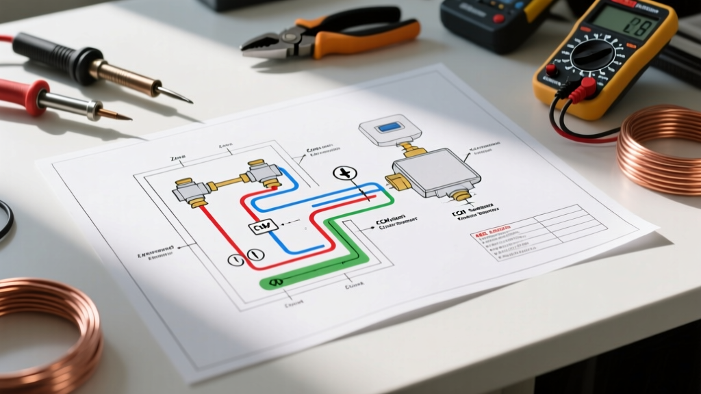
When you unroll the schematic for a modern modulating/condensing (mod/con) boiler, the diagram is typically segregated into three distinct electrical domains. Understanding these boundaries is the first step in planning your rough-in wiring.
1. Line Voltage (120VAC / 240VAC) Inputs and Outputs
This section covers the main power feed, the internal boiler pump, and external high-voltage circulators. Modern boilers require a dedicated 15A or 20A, 120VAC circuit. The wiring diagram will clearly show the Line (L), Neutral (N), and Ground (G) connections. Crucial planning note: The polarity of Line and Neutral matters on modern boilers. The control board uses the neutral path for flame rectification sensing. Reversing polarity will cause the boiler to lock out on a 'flame failure' error code, even if the igniter fires perfectly.
2. Low Voltage Control (24VAC) and Thermostat Circuits
This domain handles the 'call for heat' signals. It includes the TT (Thermostat) terminals, zone valve end switches, and aquastats. In 2026, the integration of Matter-over-Thread smart thermostats (like the latest Nest or Ecobee models) means you must also plan for a dedicated C-wire (Common) to provide continuous 24VAC power to the thermostat's Wi-Fi radio, rather than relying on parasitic power stealing from the heating circuit.
3. External Sensor and Communication Networks
High-efficiency systems rely on outdoor reset (ODR) sensors and system supply/return temperature thermistors. These are not simple switches; they are variable resistors (typically 10k Ohm or 12k Ohm at 77°F) or digital communication buses. The wiring diagram will specify whether these require standard low-voltage wire or shielded twisted-pair cables to prevent electromagnetic interference (EMI).
Pre-Installation Wire Gauge & Load Matrix
One of the most common planning failures is using a single wire type for the entire control system. Voltage drop over long runs can cause zone valves to chatter or fail to open fully. Use the following matrix to plan your wire purchases before rough-in begins.
| Component / Circuit | Typical Voltage | Recommended Wire Gauge | Max Run Length (Voltage Drop Limit) |
|---|---|---|---|
| Main Boiler Feed (Branch Circuit) | 120VAC | 12 AWG Copper (THHN/Romex) | N/A (Standard Branch Circuit Rules) |
| Internal / External Line Voltage Pumps | 120VAC | 14 AWG Copper | 50 ft |
| 24VAC Zone Valves & Thermostats | 24VAC | 18 AWG Solid (Thermostat Wire) | 100 ft (2-wire zone valve loop) |
| 0-10V DC ECM Pump Signal | 0-10V DC | 16 AWG Stranded Shielded | 150 ft |
| Outdoor Reset (ODR) Sensor | Variable Resistance | 22 AWG Twisted Pair | 250 ft |
Planning for ECM Circulators and Outdoor Reset
The era of single-speed, 3-piece cast-iron circulators is effectively over. Driven by recent U.S. Department of Energy boiler and pump efficiency guidelines, ECM pumps like the Taco 0015e or Grundfos Alpha are now standard. These pumps modulate their speed based on a 0-10V DC or PWM (Pulse Width Modulation) signal sent directly from the boiler's outdoor reset logic.
Expert Installation Tip: Never run 0-10V DC pump signal wires in the same conduit or knockout as 120VAC line voltage wires. The alternating magnetic field from the line voltage will induce 'noise' in the low-voltage signal wire, causing the ECM pump to surge, hunt, or default to a fail-safe high-speed mode, destroying your system's AFUE efficiency rating.
When reviewing the wiring diagram for boiler setups with ECM integration, locate the specific terminals for the 0-10V output. You must plan to pull a dedicated 16 AWG shielded cable from the boiler's mechanical room to the pump's junction box. Ensure the shield is grounded only at the boiler control board end to prevent ground loops.
Zone Valve Control Wiring: The 40VA Transformer Trap
Perhaps the most frequent cause of post-installation service calls in multi-zone hydronic systems is transformer burnout. Most residential boilers (including popular models from Weil-McLain and Peerless) come equipped with an internal 40VA, 24VAC control transformer.
The Math Behind the Failure
A standard Honeywell or Resideo V8043E zone valve draws approximately 8VA (roughly 0.35 Amps) during its inrush phase when the motor opens the valve. If your home has 5 heating zones, the simultaneous startup of all 5 zone valves demands 40VA (5 x 8VA). This perfectly maxes out the boiler's internal transformer. If a smart thermostat, a Wi-Fi module, or a slight voltage drop is added to the equation, the transformer overheats, tripping its internal thermal fuse or burning the trace on the main control board.
The Solution: External Isolated Relays
If your installation plan includes 4 or more zone valves, you must look past the primary wiring diagram and plan for an external control strategy.
- Upgrade the Transformer: Install an external 50VA or 75VA Class 2 transformer (e.g., Honeywell AT88D).
- Use a Switching Relay: Devices like the Taco SR506-EXP isolate the zone valve loads from the boiler. The boiler only 'sees' the dry contact closure of the relay's end-switch, which draws virtually zero VA, while the external transformer handles the heavy lifting of the zone valve motors.
Real-World Failure Modes & Edge Cases
When planning your wire routing, anticipate these specific edge cases that rarely appear in the manufacturer's basic wiring diagram:
- Phantom Calls for Heat (Induced Voltage): If 18 AWG thermostat wires are run parallel to high-voltage Romex for more than a few feet, capacitive coupling can induce a 10V-15V 'phantom' voltage on the T-stat wire. Modern high-impedance boiler control boards may misinterpret this as a closed thermostat, causing the boiler to short-cycle. Fix: Maintain a minimum 2-inch separation from line voltage, or use shielded control wire.
- Outdoor Reset Inaccuracy: If the ODR sensor wire is spliced using standard wire nuts inside an unsealed exterior wall cavity, moisture ingress will alter the resistance of the thermistor. The boiler will read this as a sudden drop in outdoor temperature and overfire the system. Fix: Use waterproof gel-filled crimps for any exterior sensor splices.
- Smart Thermostat C-Wire Starvation: Wiring a Wi-Fi thermostat to a 2-wire zone valve system without a C-wire will cause the thermostat to steal power by briefly pulsing the zone valve motor. This results in the valve clicking open and shut every few minutes. Fix: Pull a 3-wire or 5-wire 18 AWG cable during rough-in to guarantee a dedicated 24VAC Common path.
NEC Code Compliance & Safety Protocols
Electrical inspectors in 2026 are strictly enforcing NFPA 70 (National Electrical Code) Article 725 regarding Class 1 and Class 2 circuits. Boiler control wiring often blurs the line between the two. If the boiler's internal transformer is not explicitly UL-listed for Class 2 power limitation, the 24VAC wiring must be treated as Class 1. This means:
- 24VAC control wires must have 600V-rated insulation (standard 18 AWG solid thermostat wire meets this, but cheap bell wire does not).
- Class 1 (24VAC) and Line Voltage (120VAC) conductors cannot share the same raceway, enclosure, or knockout hole unless they are separated by a permanent physical barrier.
- All external boiler disconnects must be within sight of the appliance or feature a lockable breaker mechanism, per NEC Article 430 and local mechanical codes.
Finalizing Your Installation Blueprint
Interpreting the wiring diagram for boiler systems is an exercise in systems thinking. By mapping out your line voltage feeds, calculating your exact 24VAC transformer loads, and planning dedicated shielded pathways for ECM pump signals, you eliminate 90% of post-installation troubleshooting. For further technical schematics and pump integration guides, consult the Taco Comfort Solutions resource library or your specific boiler manufacturer's engineering portal before pulling your first wire.