
The Reality of Arduino Stepper Motor Wiring Failures
When building CNC routers, 3D printers, or automated camera sliders, the arduino stepper motor wiring phase is where most projects stall. Makers frequently blame 'bad code' or 'defective drivers' when a NEMA 17 motor vibrates in place or a 28BYJ-48 runs backward. In reality, over 80% of these issues stem from fundamental wiring faults: floating logic pins, missing decoupling capacitors, or incorrect coil phase pairing.
As we move through 2026, the market is flooded with ultra-cheap clone drivers. While a genuine Texas Instruments DRV8825 costs around $12, clone A4988 boards can be found for under $2. However, these clones often deviate from official schematics, using different sense resistors that completely invalidate standard Vref tuning formulas. This guide uses schematic-level troubleshooting to help you diagnose and fix your stepper motor wiring, moving beyond basic tutorials into expert-level hardware validation.
Core Wiring Diagrams & Pinout References
Before troubleshooting, you must verify your baseline wiring against standard configurations. The most common point of failure in arduino stepper motor wiring is the separation of logic power (VDD) and motor power (VMOT), and the failure to tie their grounds together.
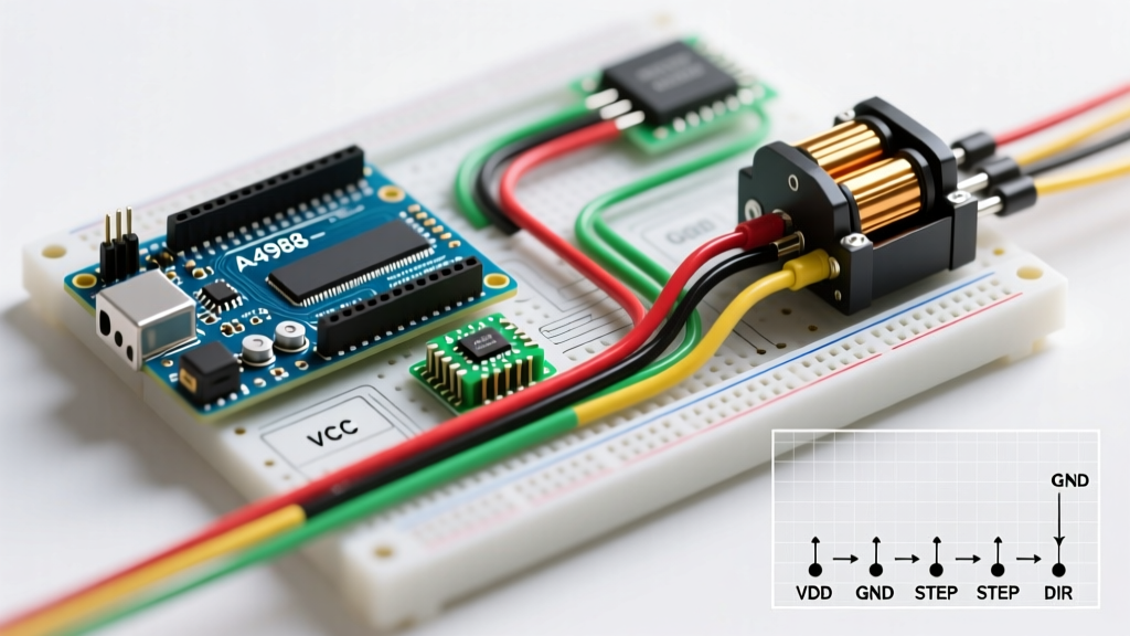
Table 1: A4988 / DRV8825 Bipolar Wiring to Arduino Uno
| Driver Pin | Arduino / Power Connection | Wiring Purpose & Troubleshooting Note |
|---|---|---|
| VMOT | External PSU (+8V to +35V) | Powers the motor coils. Must have a 100µF decoupling capacitor to GND. |
| GND (Motor) | External PSU (GND) | High-current return path. Keep traces/wires thick (18 AWG minimum). |
| VDD | Arduino 5V Pin | Logic power. Do not exceed 5.5V or you will fry the internal optoisolators. |
| GND (Logic) | Arduino GND Pin | Critical: Must be tied to Motor GND to establish a common reference voltage. |
| STEP | Arduino Digital Pin 2 | Each rising edge moves one microstep. Floating pins cause erratic stepping. |
| DIR | Arduino Digital Pin 3 | High = CW, Low = CCW. Must be stable before STEP pulse begins. |
| MS1, MS2, MS3 | Arduino 5V or GND | Microstep resolution. Never leave floating; tie to GND for full-step if unused. |
Diagnostic Troubleshooting Matrix
Use this matrix to cross-reference your physical symptoms with your wiring diagram. This eliminates guesswork and isolates the exact node of failure.
| Symptom | Probable Wiring Fault | Diagram Verification Step | Hardware Fix |
|---|---|---|---|
| Motor vibrates/buzzes but shaft does not rotate. | Coil polarity swapped or STEP frequency exceeds motor torque curve. | Check 1A/1B and 2A/2B pairs. Verify STEP pin pulse width. | Swap one coil pair (e.g., swap 1A and 1B). Lower acceleration in code. |
| Driver chip overheats instantly and shuts down (thermal trip). | Vref set too high, or missing VMOT decoupling capacitor. | Measure voltage across sense resistor. Inspect VMOT/GND cap placement. | Recalculate Vref. Solder 100µF cap directly to driver pins. |
| Motor moves erratically or skips steps randomly. | Floating MS1/MS2/MS3 pins or inadequate logic ground. | Probe MS pins with oscilloscope/multimeter. Check GND continuity. | Tie unused MS pins to GND. Add a common ground wire between PSU and Arduino. |
| Motor runs smoothly in one direction, but stalls in reverse. | DIR pin setup time violation or loose DIR jumper. | Verify DIR pin changes state at least 200ns before STEP rising edge. | Replace DIR jumper wire. Add a 10ms software delay after DIR change. |
Deep Dive: Identifying Coil Pairs Without a Schematic
Stepper motors rarely ship with reliable wiring diagrams, and wire color codes (e.g., Black/Green vs. Red/Blue) vary wildly between manufacturers like StepperOnline, LulzBot, and generic OEMs. Relying on color is a primary cause of phase-wiring errors.
The Multimeter Continuity Method
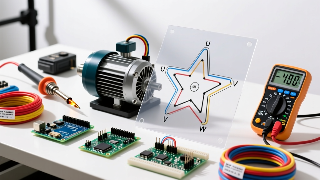
For a standard 4-wire bipolar NEMA 17 (like the popular 17HS4401S), you must identify the two distinct electromagnetic coils (Coil A and Coil B).
- Set your multimeter to resistance (Ohms).
- Probe all wire combinations. You will find two pairs that show continuity (typically 1.5Ω to 2.2Ω for NEMA 17s). Wires from different coils will show infinite resistance (OL).
- Label the pairs. Call one pair A/A' and the other B/B'.
- Connect to the driver. Connect A/A' to 1A/1B, and B/B' to 2A/2B.
Expert Tip: If the motor spins in the wrong direction after wiring, do not swap wires between Coil A and Coil B. Simply reverse the two wires of one single coil (e.g., swap 1A and 1B). This reverses the magnetic field sequence safely.
The Decoupling Capacitor: A Non-Negotiable Diagram Element
Many beginner arduino stepper motor wiring diagrams omit the bulk decoupling capacitor, or show it placed arbitrarily on a breadboard. This is a critical error.
Warning: Stepper motors are highly inductive loads. When the driver's internal MOSFETs switch off, the collapsing magnetic field generates massive voltage spikes (back-EMF). Without a local capacitor, these spikes will exceed the 35V absolute maximum rating of the A4988/DRV8825, instantly destroying the driver IC.
The Correct Implementation:
- Component: 100µF Electrolytic Capacitor, rated for at least 35V (50V preferred for 24V systems).
- Placement: The capacitor must be soldered or plugged directly adjacent to the VMOT and GND pins on the driver carrier board.
- Why Placement Matters: Long jumper wires add parasitic inductance. If the cap is 6 inches away on a breadboard, it cannot react fast enough to clamp the high-frequency voltage spike. Keep the physical loop area as small as possible.
Vref Tuning: The Electrical Missing Link
Your wiring diagram is only half the battle. The current limit potentiometer (Vref) dictates how much current flows through your wiring and motor coils. According to the Pololu A4988 Stepper Motor Driver Carrier documentation, the formula for current limiting is:
Vref = Imax × 8 × Rsense
The Clone Board Trap (2025-2026 Hardware Reality)
Authentic Allegro A4988 boards use a 0.1Ω sense resistor. If your motor is rated for 1.5A, your target Vref is 1.5 × 8 × 0.1 = 1.2V.
However, many modern clone boards manufactured in 2025 and 2026 use 0.05Ω or 0.11Ω resistors to cut costs or alter thermal profiles. If you apply the 1.2V formula to a board with a 0.05Ω resistor, you will actually push 3.0 Amps through your motor. This will melt the internal coil enamel, causing a short circuit that permanently kills the motor and the driver.
Actionable Fix: Before tuning Vref, flip the driver board over. Read the 3-digit code on the sense resistor. R10 means 0.1Ω. R05 means 0.05Ω. Adjust your math accordingly. For advanced silent operation, consider upgrading your wiring to a Texas Instruments DRV8825 or a TMC2209, which handles microstepping with significantly less acoustic noise and heat.
Expert FAQ: Advanced Wiring Scenarios
Can I wire a 6-wire unipolar stepper motor to an A4988 bipolar driver?
Yes, but you must identify the center taps. Use a multimeter to find the common wire for each coil half (it will show half the resistance to the end wires compared to end-to-end). Leave the center taps completely disconnected and insulated. Wire only the four outer end-wires to the A4988's 1A, 1B, 2A, and 2B pins. This effectively converts the motor to a bipolar configuration, yielding roughly 30% more holding torque.
Why does my Arduino reset every time the stepper motor starts moving?
This is a classic ground-loop and voltage sag issue caused by poor power supply wiring. When the stepper motor draws peak current (often 2A+ per phase), it causes a momentary voltage drop on the power rail. If your Arduino is powered via the barrel jack from the same supply, or if the logic ground wire is too thin (e.g., 24 AWG breadboard jumper), the Arduino's 5V regulator drops out, triggering a hardware reset. Fix: Power the Arduino via USB from an isolated source, or use a dedicated buck converter (like an LM2596) wired directly to the battery/PSU terminals, bypassing the motor's transient current paths.
Do I need flyback diodes on the motor wires?
No. Modern chopper drivers like the A4988, DRV8825, and TMC2209 have internal fast-recovery flyback diodes integrated into their H-bridge MOSFETs. Adding external diodes in your arduino stepper motor wiring harness will only increase parasitic capacitance and interfere with the driver's high-speed PWM decay modes. Rely on the bulk 100µF VMOT capacitor for system-level protection instead.
For further software-side troubleshooting regarding step-pulse timing and acceleration ramps, refer to the official Arduino Stepper Library Documentation and consider upgrading to the AccelStepper library for multi-motor synchronization.