
The Core Architecture of Oil Furnace Electrical Systems
Deciphering the wiring diagram for oil furnace systems requires a fundamental understanding of how high-voltage ignition, low-voltage flame sensing, and line-voltage blower operations intersect. Unlike natural gas or propane systems, oil furnaces rely on atomization and high-voltage arcing to ignite the fuel. According to the U.S. Department of Energy, modern oil heating systems operate at an AFUE (Annual Fuel Utilization Efficiency) of up to 95%, but achieving this efficiency relies entirely on the precise electrical sequencing managed by the primary control relay.
A standard warm-air oil furnace electrical system is divided into two distinct circuits: the 120V AC primary line voltage and the 24V AC secondary control voltage. The 120V circuit powers the blower motor, the oil valve solenoid, and the primary side of the ignition transformer. The 24V circuit, typically stepped down via an internal transformer within the primary control or an external aquastat/fan-limit switch, handles the thermostat call for heat. Understanding the wiring diagram for oil furnace components means mapping how these two circuits communicate to execute a safe, timed ignition sequence.
Primary Control Terminals: The Brain of the Operation
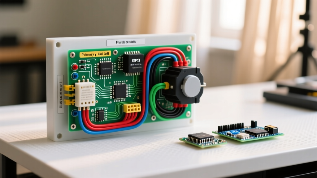
The primary control (often referred to as the burner relay) is the central node in any oil furnace wiring diagram. It monitors the thermostat, powers the ignition and motor, and verifies the flame via the cad cell. While legacy systems like the Honeywell R8184G have been industry staples for decades, modern digital controls like the Beckett GeniSys 7505 offer advanced diagnostics. Below is a breakdown of the standard terminal configurations you will encounter on the wiring diagram.
Legacy Analog Controls (e.g., Honeywell R8184G / Resideo)
- T-T (Thermostat Terminals): These connect to the 24V thermostat circuit. When the thermostat calls for heat, it closes the circuit across T-T, energizing the internal relay.
- B1-B2 (Line Voltage In): B1 receives 120V hot from the service switch or fan/limit switch. B2 is the neutral return. This provides the main power to the control's internal motor and switching relays.
- CAD (Cad Cell Terminals): Two yellow wires connect here, leading to the cad cell photocell mounted on the burner tube. The control measures the electrical resistance across these terminals to verify flame presence.
- IGN (Ignition): Outputs 120V to the primary side of the ignition transformer during the pre-purge and trial-for-ignition periods.
- MTR (Motor): Outputs 120V to the blower motor and the oil valve solenoid once the cad cell verifies a stable flame.
Modern Digital Controls (e.g., Beckett GeniSys 7505)
Modern controls utilize a multi-pin terminal strip rather than individual screw terminals. The 7505 features a 10-pin connector where Pin 1 and 2 handle the 120V line input, Pin 3 and 4 handle the 24V thermostat input, and Pins 7 and 8 are dedicated to the cad cell. The GeniSys 7505 also introduces an interrupted duty sequence with a built-in 15-second trial for ignition, a 60-second post-purge, and a 3-strike lockout protocol that fundamentally alters how technicians troubleshoot the wiring diagram.
Wire Gauge and Color Coding Matrix
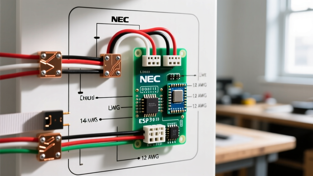
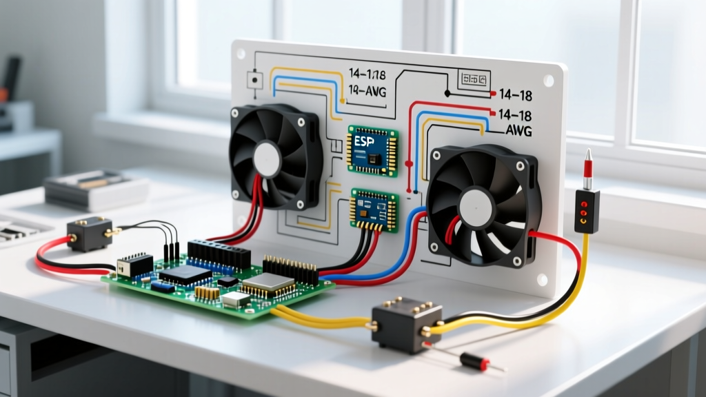
Adhering to proper wire gauge and color coding is critical for safety and NEC compliance. The National Fire Protection Association (NFPA 70) dictates strict standards for appliance wiring. Below is the standard matrix used by HVAC professionals when wiring or rewiring an oil furnace control board.
| Circuit Function | Wire Gauge (AWG) | Standard Jacket Color | Voltage / Signal Type |
|---|---|---|---|
| 120V Main Line Feed | 14 AWG | Black (Hot) / White (Neutral) | 120V AC, 60Hz |
| Thermostat Control | 18 AWG | Red / White | 24V AC |
| Cad Cell Flame Sensor | 18 AWG | Yellow / Orange | Low Voltage DC/AC (Resistance) |
| Ignition Transformer Primary | 14 AWG | Black with Orange Stripe | 120V AC (Switched) |
| Ignition Transformer Secondary | High Voltage Lead | Black (Silicone Insulated) | 10,000V - 14,000V AC |
The Cad Cell Flame Sensor: Resistance Parameters & Edge Cases
The cad cell (cadmium sulfide photocell) is the most critical safety device in the oil furnace wiring diagram. It acts as a variable resistor whose resistance drops dramatically when exposed to the specific light spectrum of an oil flame. If the primary control does not see the correct resistance drop within the trial-for-ignition window, it will shut off the oil valve to prevent raw fuel from flooding the combustion chamber.
⚠️ High-Voltage Warning: Never attempt to measure the secondary side of the ignition transformer with a standard multimeter. The transformer outputs between 10,000 and 14,000 volts, which will instantly destroy standard testing equipment and poses a lethal shock hazard. Always test flame verification on the low-voltage cad cell side.
Resistance Thresholds by Manufacturer
Not all primary controls interpret cad cell resistance identically. When troubleshooting a flame-sensing failure, you must know the specific threshold of the control board installed:
- Honeywell / Resideo (R8184 Series): Requires a light resistance of under 350 ohms. If resistance hovers around 400 ohms, the control will not pull in the MTR relay, resulting in a lockout.
- Carlin (CR series): Generally more forgiving, requiring a light resistance of under 1,200 ohms.
- Beckett (GeniSys 7505): Requires a light resistance of under 1,000 ohms, but also monitors for a dark resistance of greater than 20,000 ohms before the ignition sequence begins to ensure the sensor isn't shorted or exposed to ambient light.
Edge Case Failure Mode: A common field issue is oil soot accumulation on the cad cell eye. Even a microscopically thin layer of soot can raise the resistance from 200 ohms to 600 ohms, causing a false lockout. Always clean the cad cell eye with isopropyl alcohol and a lint-free cloth before condemning the sensor or the primary control.
Integrating the Fan/Limit Switch (Honeywell L4064)
In a warm-air oil furnace, the fan/limit switch bridges the gap between the thermostat's 24V call for heat and the 120V line voltage feeding the primary control. The Honeywell L4064 is the industry standard. The wiring diagram routes the 120V hot leg from the service disconnect directly into the "Line" terminal of the L4064. The internal limit switch (normally closed, set to trip at 200°F) routes the power out of the "Load" terminal and directly into the B1 terminal of the primary control.
The fan switch portion (normally open) operates independently based on plenum temperature. Standard field settings dictate the fan turns ON at 130°F and OFF at 100°F. If the blower motor fails to start but the burner fires, the limit switch will eventually trip at 200°F, cutting 120V power to the B1 terminal and shutting down the entire burner assembly to prevent heat exchanger damage.
Troubleshooting: Hard vs. Soft Lockouts
When referencing the wiring diagram for oil furnace diagnostics, understanding the difference between interrupted duty and lockout sequences is vital. Older controls like the R8184G operate on an "interrupted duty" basis—meaning if the flame fails, the control shuts off the oil valve but will immediately attempt to reignite if the T-T circuit remains closed. This can lead to dangerous fuel accumulation.
Modern controls listed by the Air-Conditioning, Heating, and Refrigeration Institute (AHRI) utilize "interrupted duty with lockout." If the Beckett 7505 fails to detect flame within 15 seconds, it enters a 60-second post-purge to clear unburned gases, then retries. After three consecutive failures, the control enters a Hard Lockout. The internal LED will glow solid red, and the control will ignore any further T-T calls for heat. To reset a hard lockout, a technician must either interrupt the 120V line power for a full 60 seconds or press the physical reset button on the GeniSys faceplate for exactly 1 to 2 seconds. Holding it longer than 3 seconds will put the control into a restricted 15-minute lockout mode.
NEC Compliance and Grounding Requirements
The wiring diagram for an oil furnace is not complete without addressing grounding. NFPA 70 (NEC) Article 422 requires that all major appliances be properly grounded via a dedicated equipment grounding conductor. In oil furnaces, grounding is not just a safety precaution; it is a functional requirement for ignition.
The ignition transformer steps 120V up to 14,000V. The secondary side of the transformer is grounded to the transformer chassis, which in turn is grounded to the furnace frame and the earth ground. The high-voltage spark arcs from the ignition electrode, across the burner nozzle, to the grounded retention head. If the furnace lacks a proper earth ground, or if the retention head is corroded and isolated from the chassis, the spark will seek an alternative path to ground—often arcing back through the primary control or the oil line, causing catastrophic component failure. Always verify continuity between the furnace chassis and the main electrical panel's ground bus bar before finalizing any control board replacement.