
Understanding the Wiring Diagram for Car Audio Capacitor Circuits
Car audio capacitors bridge the critical gap between your vehicle's alternator output and the transient current demands of high-power amplifiers. When a subwoofer demands a sudden 100-amp burst to reproduce a heavy bass note, the vehicle's electrical system (typically outputting 14.4V at 120A) can experience severe voltage sag. This results in dimming headlights, clipped audio signals, and potential damage to sensitive onboard electronics. A properly wired capacitor mitigates this by acting as a localized, high-speed energy reservoir.
However, simply buying a 1.5 Farad capacitor and hooking it up haphazardly will not yield results. The wiring diagram for car audio capacitor setups requires strict adherence to distance rules, wire gauge specifications, and pre-charging protocols. According to the Consumer Technology Association (CTA) mobile electronics standards, improper installation can lead to catastrophic inrush currents and localized electrical fires.
The Core Topology: Visualizing the Circuit
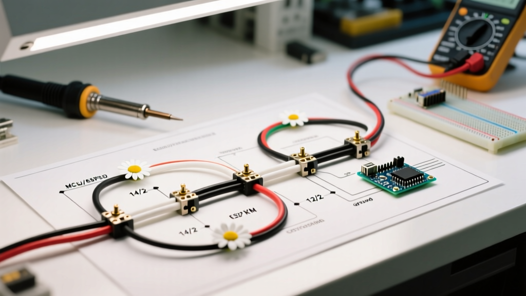
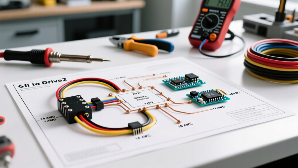
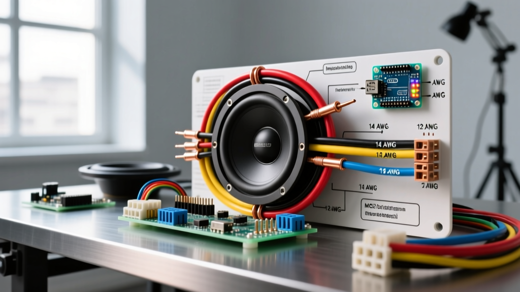
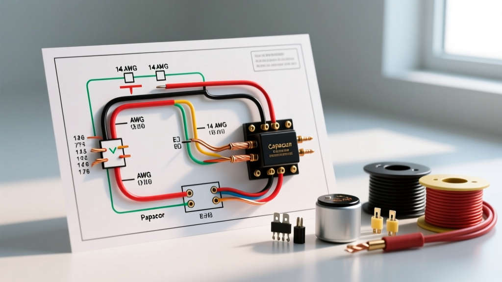
Unlike amplifiers that draw continuous current, a capacitor is wired in parallel with the amplifier's power supply. It does not sit in series with the audio signal or the main power feed. Here is the exact logical flow of a compliant wiring diagram:
- Battery Positive Terminal → Main ANL Fuse (within 18 inches of battery).
- Main Power Wire → Runs through the firewall to the trunk/hatch area.
- Distribution Block → Power wire terminates at a fused or unfused distribution block.
- Branch 1 (Amplifier) → Short jumper wire from the block to the amplifier's +12V terminal.
- Branch 2 (Capacitor) → Short jumper wire from the block to the capacitor's positive terminal.
- Ground Topology → Capacitor negative terminal grounds to the exact same chassis point as the amplifier, or a dedicated bare-metal point within 12 inches.
Component Selection & Wire Gauge Matrix
As of 2026, the market has largely shifted away from CCA (Copper-Clad Aluminum) wire due to its higher resistance and susceptibility to galvanic corrosion. Always use OFC (Oxygen-Free Copper). Below is the reference matrix for matching your system's RMS power to the correct wire gauge and capacitor sizing.
| System RMS Power | Recommended Wire Gauge (OFC) | Capacitor Size (Farads) | Example 2026 Model | Approx. Cost |
|---|---|---|---|---|
| Up to 500W | 8 AWG | 0.5F - 1.0F | Rockford Fosgate RFC1D | $130 - $150 |
| 500W - 1200W | 4 AWG | 1.0F - 1.5F | Kicker KCP10 (Digital) | $180 - $210 |
| 1200W - 2500W | 1/0 AWG | 2.0F - 5.0F | Stetsom STX20 | $320 - $380 |
| 2500W+ | 2/0 AWG or Dual 1/0 AWG | 5.0F - 10.0F+ | Custom Lithium-Ion Banks | $600+ |
Note: The general rule of thumb is 1 Farad per 1,000 watts of RMS power, though modern high-efficiency Class D amplifiers often require slightly less capacitance than older Class AB designs.
The Pre-Charge Protocol: Preventing Inrush Current Damage
CRITICAL WARNING: Never connect an uncharged car audio capacitor directly to a 12V power source. An empty capacitor acts as a dead short circuit. The resulting inrush current can exceed 500 amps for a fraction of a second, instantly vaporizing your main ANL fuse, welding relay contacts, or triggering your vehicle's CAN-bus system to throw critical fault codes.
To safely charge the capacitor, you must limit the current flow during the initial connection. This is done using a pre-charge resistor or a standard 12V automotive test light.
Method 1: The Ceramic Power Resistor (Recommended)
Use a 1-ohm, 20-watt ceramic power resistor. Connect the resistor between the positive power wire and the capacitor's positive terminal. The resistor limits the inrush current to a safe ~12 amps. Wait 30 to 60 seconds. Once the resistor stops getting hot, the capacitor is charged. Remove the resistor and connect the positive wire directly to the terminal.
Method 2: The 12V Test Light
If you do not have a resistor, use a standard 12V incandescent test light (not LED). Connect the test light between the power wire and the capacitor's positive terminal. The bulb will illuminate brightly as current rushes in, then slowly dim and extinguish as the capacitor reaches 12V. Once the light is completely off, the capacitor is charged.
Step-by-Step Installation Sequence
- Disconnect the Battery: Always remove the negative terminal from the vehicle's battery before routing any power wires.
- Mount the Capacitor: Secure the capacitor using its provided brackets. Ensure it is not resting against sharp metal edges or near moving components like trunk hinges.
- Wire the Ground: Sand away paint and clear coat from the chassis ground point using 80-grit sandpaper. Attach the ground wire using a brass or copper ring terminal. Coat the area with dielectric grease to prevent oxidation.
- Connect the Positive (with Pre-Charge): Follow the pre-charge protocol detailed above. Do not bypass this step.
- Verify Voltage: Turn on the vehicle and the head unit. Check the capacitor's digital display (if equipped) or use a multimeter to verify it reads between 13.8V and 14.4V.
The 18-Inch Placement Rule and Grounding Topology
The most common mistake in car audio wiring is placing the capacitor near the battery or in the middle of the trunk, far away from the amplifier. The capacitor must be mounted within 18 inches (45 cm) of the amplifier's positive terminal.
Why? A capacitor regulates and stabilizes the voltage at its own physical terminals. If you place it 4 feet away from the amplifier, it successfully stabilizes the voltage at the capacitor, but the 4 feet of wire between the capacitor and the amplifier still possesses inherent resistance and inductance. By the time the current reaches the amplifier, voltage sag will still occur. Placing it within 18 inches ensures the amplifier draws directly from the stabilized reservoir.
Furthermore, the capacitor's ground must be tied into the amplifier's ground. If they share different ground points, a phenomenon known as a 'ground loop' can occur, introducing a high-pitched alternator whine into your audio signal.
Advanced Troubleshooting: ESR and Dielectric Failure Modes
Capacitors are not immortal components. Over time, they degrade, and understanding these failure modes is crucial for long-term system maintenance. As detailed in foundational electronics theory by All About Circuits, the internal chemistry of electrolytic capacitors dictates their lifespan.
- Increased ESR (Equivalent Series Resistance): As the internal electrolyte dries out over 5 to 7 years, the ESR rises. A healthy car audio capacitor should have an ESR below 20 milliohms. If it creeps above 50 milliohms, it can no longer discharge energy fast enough to keep up with subwoofer transients, rendering it useless. You can test this using a dedicated ESR meter.
- Dielectric Breakdown: If your vehicle's voltage regulator fails and sends 18V or more through the system, the capacitor's internal dielectric layer can puncture. This causes a dead short, leading to rapid heating, venting of the electrolyte, and potential casing rupture. Most premium 2026 models include over-voltage protection circuits that disconnect the cap at 17V.
- Parasitic Drain: If your vehicle battery dies after sitting for 48 hours, the capacitor's internal leakage current may be too high. Disconnect the capacitor and measure the draw; if it exceeds 5mA while the car is off, the unit is defective and must be replaced.
Frequently Asked Questions
Do I need a capacitor if I have a high-output alternator?
If you have upgraded to a 250A+ alternator and added a secondary AGM or Lithium battery in the trunk, a traditional electrolytic capacitor becomes largely redundant. The secondary battery provides vastly more energy storage (measured in Amp-hours rather than Farads) and handles sustained voltage drops better than a capacitor, which only handles micro-second transients.
Can I wire multiple capacitors together?
Yes. Wiring two 1.0F capacitors in parallel yields a total capacitance of 2.0F. Ensure both are pre-charged individually before connecting them to the main distribution block to avoid cross-charging inrush currents between the units.
Why does my capacitor display drop to 11V when the bass hits?
This indicates that the capacitor is doing its job by discharging stored energy to support the amplifier. However, if it drops below 10.5V consistently, your system's total power demand exceeds the combined output of your alternator, battery, and capacitor bank. You must either reduce the amplifier gain or upgrade your vehicle's charging system.