
The Critical Divide: NEC vs. IEC 3-Phase Color Standards
When wiring a 3-phase induction motor, confusing supply line colors with internal motor lead colors is a leading cause of catastrophic equipment failure, blown fuses, and reverse-rotation damage to coupled loads like centrifugal pumps. The first step in any motor wiring tutorial is understanding the governing regional standards. In North America, the National Electrical Code (NEC) dictates supply conductor colors, while the International Electrotechnical Commission (IEC) governs most of the globe.
According to the NFPA 70 (NEC), 3-phase supply wiring colors change based on the system voltage. This is a critical distinction that many DIYers and junior electricians miss when transitioning from 208V to 480V systems.
| System Voltage | Phase A (L1) | Phase B (L2) | Phase C (L3) | Neutral (If applicable) | Equipment Ground |
|---|---|---|---|---|---|
| 208Y/120V (NEC) | Black | Red | Blue | White / Grey | Green / Bare |
| 480Y/277V (NEC) | Brown | Orange | Yellow | White / Grey | Green / Bare |
| 480V Delta (NEC) | Brown | Orange | Yellow | N/A | Green / Bare |
| Global 400V (IEC 60446) | Brown | Black | Grey | Blue | Green/Yellow Stripe |
CRITICAL SAFETY WARNING: Never assume the orange wire is always L2. In older legacy 240V Delta high-leg systems, Orange designates the high leg (Phase B to Neutral = 208V). Connecting a 120V motor control circuit to the high leg will instantly destroy the control transformer. Always verify with a True-RMS multimeter before terminating.
Decoding Motor Lead Markings: NEMA (T-Leads) vs. IEC (U/V/W)
While the supply wires follow the color codes above, the motor internal leads follow an entirely different nomenclature. This is where the phrase 'electrical wiring colours 3 phase' becomes a misnomer for the actual motor terminals. Motor leads are typically unmarked black or white wires with stamped metal ferrules or printed heat-shrink tags.
NEMA Standard (North America) 9-Lead Dual Voltage Motors
Most industrial 3-phase motors in the US (such as the popular Baldor-Reliance Super-E series) are 9-lead dual-voltage Wye (Star) or Delta wound. They use T-designations:
- T1, T2, T3: Line connections for high voltage (460V).
- T4, T5, T6, T7, T8, T9: Internal winding taps used to reconfigure the motor for low voltage (230V) or high voltage.
IEC Standard (Global) 6-Lead Motors
IEC motors use a U, V, W designation, which directly correlates to the phases but does not use color codes for the pigtails. Instead, they rely on alphanumeric stamps:
- U1, V1, W1: Start of windings 1, 2, and 3.
- U2, V2, W2: Finish of windings 1, 2, and 3.
Step-by-Step Tutorial: Wiring a 5HP 460V 3-Phase Motor
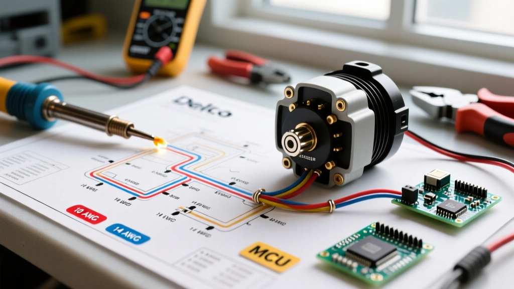
Let us walk through a real-world scenario: wiring a Baldor CEM3615T (5HP, 1750 RPM, 208-230/460V) to a 480Y/277V supply panel. At 460V, this motor draws approximately 6.8 Amps at full load. Based on NEC Article 430.22, we must size conductors at 125% of the Full Load Amps (FLA), which equals 8.5 Amps. A 14 AWG THHN wire is technically sufficient (rated 20A), but standard industrial practice and voltage drop considerations over long runs dictate using 10 AWG THHN for mechanical durability.
- Lockout/Tagout (LOTO): De-energize the 480V breaker. Verify zero energy using a CAT III rated multimeter (e.g., Fluke 117) phase-to-phase and phase-to-ground.
- Prepare Supply Conductors: Pull three 10 AWG THHN wires (Brown, Orange, Yellow) and one 10 AWG Green ground through 3/4-inch EMT conduit. Strip exactly 3/4 inch of insulation using a precision wire stripper to avoid nicking the copper, which creates a hot-spot failure point under load.
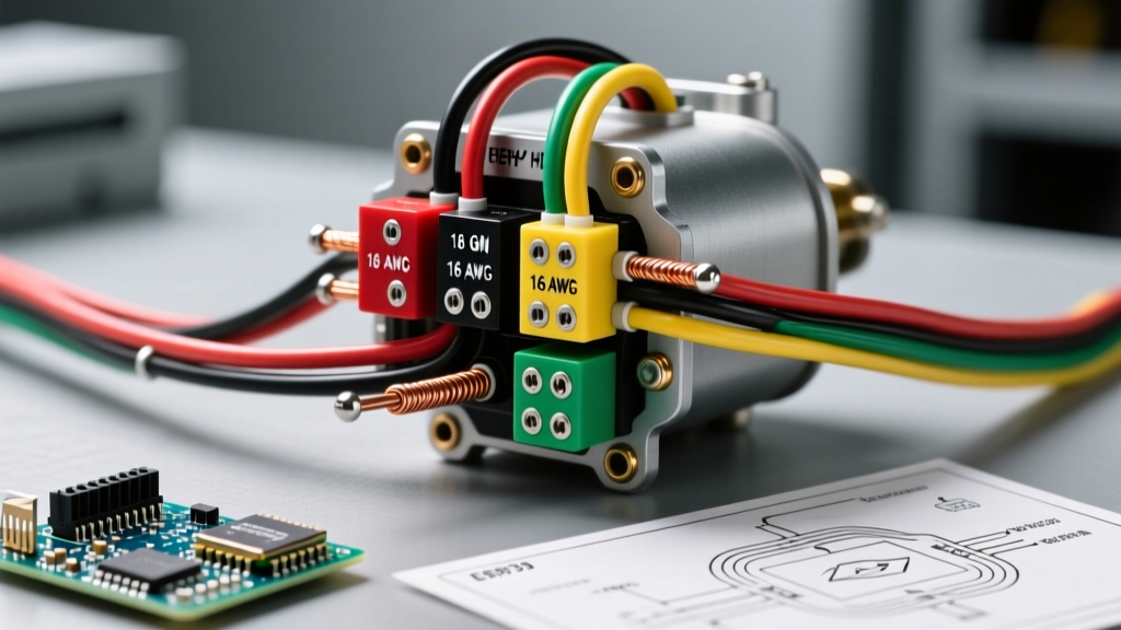
- Configure Motor for High Voltage (460V Wye): Open the motor peckerhead (connection box). For a 9-lead Wye motor, the high-voltage wiring diagram requires you to group and insulate T4-T5-T6 together with a wire nut. The supply lines connect to T1, T2, and T3. T7, T8, and T9 are not used in this specific high-voltage Wye configuration and must be individually insulated.
- Terminate and Torque: Connect Brown to T1, Orange to T2, and Yellow to T3. Connect the Green ground to the motor frame grounding lug. Using a calibrated torque screwdriver, tighten the terminal block screws to 35 in-lbs (verify against the specific motor nameplate). Under-torquing causes arcing; over-torquing strips the brass threads.
- Phase Rotation Check: Before coupling the motor to the load, use a phase rotation meter like the Fluke PRV240 to ensure the L1-L2-L3 sequence matches the motor's required clockwise rotation. Reversing rotation on a screw compressor can destroy the airend in under 3 seconds.
VFD Integration: Why Output Wiring Colors and Shielding Matter
When introducing a Variable Frequency Drive (VFD) like the Allen-Bradley PowerFlex 525, the standard electrical wiring colours 3 phase rules apply to the input side (L1, L2, L3). However, the output side (U, V, W to the motor) requires specialized cabling.
Standard THHN in conduit is highly susceptible to the high-frequency PWM (Pulse Width Modulation) switching of the VFD, which can cause reflected wave phenomena and bearing fluting. For VFD applications, always use symmetrically shielded VFD cable (e.g., Belden 14 AWG 3-conductor with continuous corrugated aluminum armor and three symmetric ground wires). The shield must be terminated with a 360-degree EMC gland at both the VFD and the motor peckerhead to safely bleed off capacitive coupling currents to the DOE recommended motor grounding systems.
VFD Input vs. Output Color Mapping
- VFD Input (Grid to Drive): Follows standard NEC colors (Brown, Orange, Yellow for 480V).
- VFD Output (Drive to Motor): Typically uses Black conductors with printed numbers (1, 2, 3) inside a shielded jacket. Do not use standard colored THHN for VFD output runs longer than 15 feet.
Troubleshooting Common 3-Phase Motor Wiring Failures
Even with perfect color adherence, 3-phase motors experience specific failure modes related to wiring errors:
- Single-Phasing: If one phase (e.g., the Yellow wire) loses connection due to a loose terminal, the motor will attempt to run on two phases. Current in the remaining two phases will spike by 173%, rapidly melting the winding insulation. Modern motor protection relays (like the Eaton EMT300) detect this phase-loss within 2 seconds.
- Wrong Voltage Tap (Low Voltage on High Supply): If you accidentally wire the 9-lead motor for 230V (paralleling the windings) but supply it with 460V, the magnetic core will saturate instantly. The motor will draw locked-rotor current (up to 60 Amps for a 5HP motor) and trip the breaker immediately, often causing severe acoustic trauma and winding damage.
- Neutral-to-Ground Bonding in Peckerhead: Never connect a neutral wire to a 3-phase motor frame. The motor frame must only be connected to the Equipment Grounding Conductor (EGC). A neutral connection here will cause ground fault protection (GFCI/GFPE) devices to nuisance trip due to normal capacitive leakage currents.
Frequently Asked Questions
Can I swap two phases to reverse motor direction?
Yes. Swapping any two of the three supply lines (e.g., swapping Brown and Orange, while leaving Yellow on T3) will reverse the rotating magnetic field and change the motor's shaft direction. Always perform this swap at the motor starter or VFD output, never inside the motor peckerhead, to maintain standardized wiring for future maintenance.
What if my motor leads are faded and unmarked?
If the T-lead tags have degraded, do not guess. Use a multimeter in continuity mode to map the winding pairs. In a 9-lead Wye motor, you will find three distinct pairs with continuity (T1-T4, T2-T5, T3-T6) and a common star point grouping (T7-T8-T9). For detailed resistance testing procedures, refer to the NFPA 70B Recommended Practice for Electrical Equipment Maintenance.