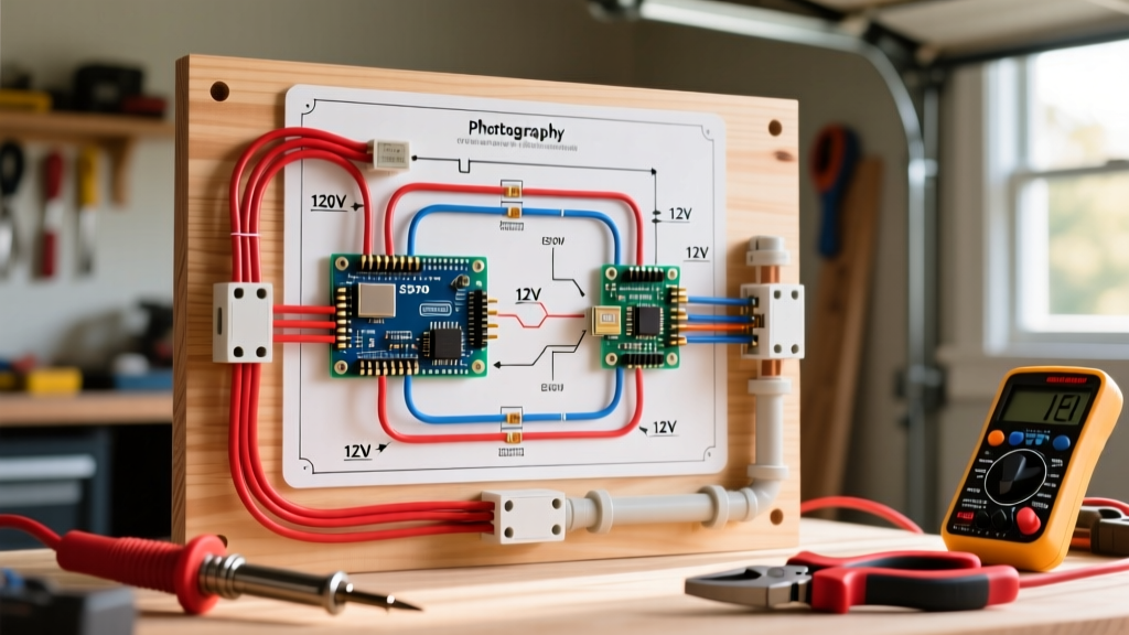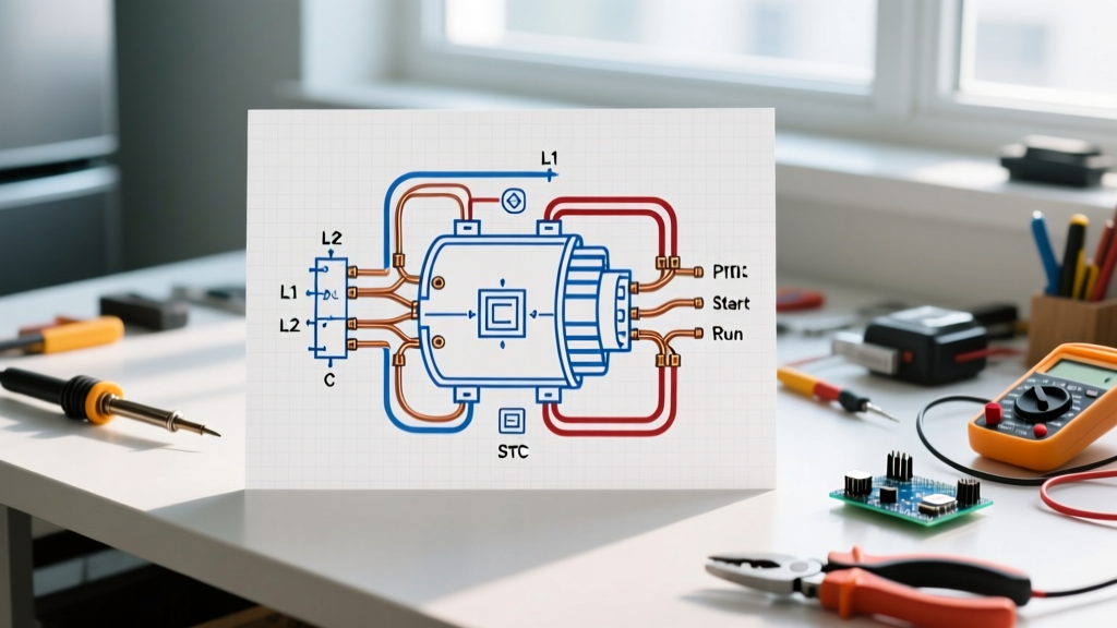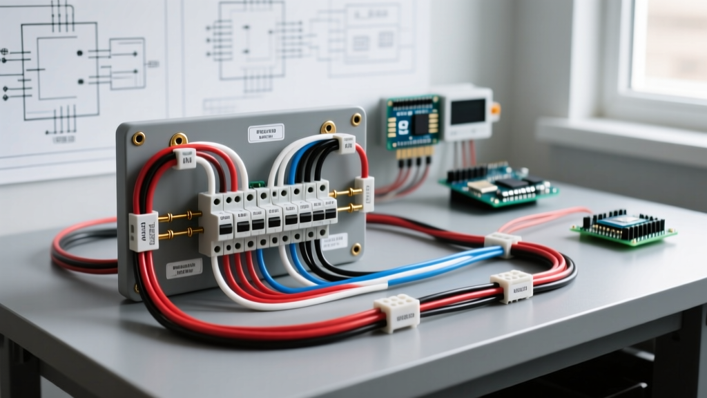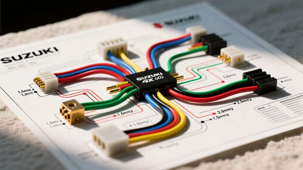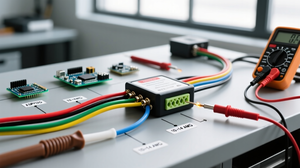

Introduction: The Brake Controller as a Critical DC Appliance
When outfitting a tow vehicle, the electronic brake controller is arguably the most critical DC appliance you will install. Unlike simple 12V lighting circuits, a brake controller manages high-current inductive loads and requires precise signal inputs to function safely. As of 2026, advanced proportional models like the Tekonsha Prodigy P3 (Model 90195) and the Redarc Tow-Pro Elite (EBRH-ACCV3) dominate the market, ranging from $160 to $240. However, even the most sophisticated internal accelerometers and microprocessors are useless if the underlying wiring diagram for a trailer brake controller is executed poorly.
This comprehensive appliance wiring tutorial breaks down the exact circuitry, wire gauge requirements, and pinout configurations needed to install a brake controller safely. Whether you are upgrading an older time-delayed unit or installing a modern proportional system from scratch, adhering to these electrical standards is non-negotiable for safe towing.
Understanding the 7-Way RV Connector Pinout
Before running wires under the dash, you must understand the destination. The standard 7-way RV blade connector is the universal interface between your tow vehicle and the trailer's electric brakes. According to standards maintained by the RV Industry Association (RVIA), the pinout must strictly follow color-coded conventions to prevent cross-circuiting, which can instantly fry a brake controller's internal logic board.
| Pin Position | Function | Standard Wire Color | Recommended Gauge | Typical Amperage |
|---|---|---|---|---|
| 1 (Ground) | White - System Ground | White | 10 AWG | Up to 40A return |
| 2 (Tail/Running) | Brown - Clearance/Tail Lights | Brown | 14 AWG | 5A - 10A |
| 3 (Left Turn/Stop) | Yellow - Left Turn & Stop | Yellow | 12 AWG | 10A - 15A |
| 4 (Right Turn/Stop) | Green - Right Turn & Stop | Green | 12 AWG | 10A - 15A |
| 5 (Electric Brakes) | Blue - Brake Output Power | Blue | 10 AWG or 12 AWG | 12A - 35A+ |
| 6 (12V Auxiliary) | Black/Red - 12V Battery Charge | Black | 10 AWG | 20A - 40A |
| 7 (Center Aux) | Purple - Reverse Lights/Aux | Purple | 14 AWG | 5A - 10A |
Core Wiring Diagram for a Trailer Brake Controller
A standard brake controller requires four primary wire connections to operate. While the exact plug-and-play harness varies by vehicle make and model, the fundamental DC circuit remains identical across all platforms.
Step 1: The Main Power Circuit (12V+)
The main power wire (typically Black on the controller pigtail) must be routed directly to the vehicle's positive battery terminal. Never splice this wire into an existing fuse box circuit or ignition switch. Electric brakes draw massive transient current spikes—up to 12 amps per brake assembly. For a dual-axle trailer (4 brakes), you are looking at 48 amps of peak draw.
- Wire Gauge: Use stranded 10 AWG TXL (cross-linked polyethylene) automotive wire for superior heat and abrasion resistance.
- Overcurrent Protection: Install a 30-Amp Maxi fuse or a 40-Amp circuit breaker within 6 inches of the battery positive terminal. This protects the main power cable from melting in the event of a dead short.
Step 2: The Ground Circuit
The ground wire (typically White) is just as critical as the power feed. A poor ground is the number one cause of the infamous 'SH' (Short) or 'C' (Connection Lost) error codes on digital displays.
- Routing: Run the 10 AWG white wire directly to the negative battery terminal or a dedicated, unpainted chassis ground bolt that shares a direct path to the battery negative.
- Preparation: Sand away all paint, primer, and rust down to bare metal. Apply a dab of dielectric grease over the ring terminal after tightening to prevent galvanic corrosion.
Step 3: The Stoplight Switch Signal (Input)
The red wire on the controller pigtail is the 'wake-up' signal. It tells the controller's microprocessor that the driver has pressed the brake pedal, prompting it to send power to the trailer brakes.
Expert Warning: You must splice into the cold side of the vehicle's brake light switch. If you accidentally tap the hot side, or tap into a combined turn-signal/brake circuit (common on older European imports), the brake controller will activate every time you use a turn signal, locking up the trailer brakes mid-corner.
Use a digital multimeter to verify the wire. It should read 0V with the pedal released, and exactly 12V-14V only when the pedal is depressed. Use a solder-seal butt connector and wrap it in friction tape; avoid cheap crimp connectors that vibrate loose over time.
Step 4: The Brake Output Wire (To the 7-Way)
The blue output wire carries the modulated DC voltage from the controller back to the 7-way connector's Pin 5. Because this wire travels the entire length of the vehicle's undercarriage, it is highly susceptible to voltage drop and physical damage.
- Wire Gauge: 10 AWG is strongly recommended for runs exceeding 15 feet to minimize voltage drop. 12 AWG is acceptable only for short-bed pickups with short runs.
- Routing: Run the blue wire inside a split-loom corrugated conduit, secured with UV-resistant zip ties every 12 inches. Keep it away from exhaust manifolds and moving suspension components.
Proportional vs. Time-Delayed: Wiring Differences
While the physical wires are the same, how the appliance processes the inputs differs drastically. Understanding this helps in troubleshooting signal issues.
| Feature | Proportional Controllers (e.g., Prodigy P3) | Time-Delayed Controllers (e.g., Tekonsha Voyager) |
|---|---|---|
| Internal Sensor | 3-Axis Accelerometer (Requires level mounting) | None (Relies purely on pedal pressure duration) |
| Stoplight Wire Role | Triggers the accelerometer to read vehicle deceleration | Initiates a pre-set timing ramp-up curve |
| Mounting Constraints | Must be mounted within a specific degree range (usually 70° to -20°) | Can be mounted in any orientation, even upside down |
| Pricing (2026 Avg) | $160 - $240 | $45 - $80 |
Common Failure Modes and Edge Cases
Even with a perfect wiring diagram for a trailer brake controller, environmental factors and edge cases can cause system failures. Here is how to diagnose the most common issues based on manufacturer troubleshooting guidelines and field experience.
The 'Voltage Drop' Phantom
If your controller display reads 10.0 volts output, but the trailer brakes feel weak, you are experiencing voltage drop. A 50-foot run of 12 AWG copper wire carrying 20 amps will drop nearly 3.2 volts. By the time the power reaches the trailer's brake magnets, they are only receiving 8.8 volts, resulting in a 40% loss in braking torque. Solution: Upgrade the blue output wire and the white ground wire on the trailer side to 10 AWG.
Ground Loop and Backfeed Issues
If the brake controller powers on and displays an error code even when the vehicle is off, you likely have a ground loop or backfeed. This happens when the trailer's running lights (brown wire) find a path to ground through the brake magnet coils because the main 7-way ground pin (white) is corroded. The 12V from the tail lights backfeeds into the blue brake circuit, tricking the controller. Solution: Clean the 7-way pins with contact cleaner and ensure the trailer's main ground to the chassis is pristine.
Blown Stoplight Fuses
If splicing the red wire causes the vehicle's interior dash lights or cruise control to fail, you have tapped into a CAN-bus controlled circuit or a shared BCM (Body Control Module) line. Modern vehicles use multiplexed signals rather than simple 12V analog switches. Solution: Use a dedicated CAN-bus signal extractor module (like the Curt 56284 or Tekonsha 118675) which safely reads the digital data packets and outputs a clean, isolated 12V analog signal for the brake controller's red wire without drawing current from the vehicle's sensitive logic boards.
Final Inspection and Safety Verification
Before connecting a trailer, perform a dry-run test. According to safety advisories from the National Highway Traffic Safety Administration (NHTSA), ensuring your tow rig's electrical systems are fully operational is a primary defense against highway jackknifing and loss-of-control incidents.
- Static Test: Turn the ignition to the 'ON' position. The controller should light up. Slide the manual override lever fully to the left. Use a multimeter at the 7-way Pin 5; it should read within 0.5V of your battery voltage.
- Pedal Test: Press the brake pedal. The controller should display a power output setting. Verify Pin 5 shows the modulated voltage corresponding to your dial setting.
- Physical Pull Test: Hitch the trailer in a safe, empty lot. Set the gain to 6.0. Drive at 15 MPH and apply the manual override. The trailer brakes should lock up or pull the vehicle to a firm, straight stop without swerving.
By treating your brake controller not just as an accessory, but as a high-current DC appliance requiring precision wiring, you ensure maximum safety, longevity, and performance for every tow.