
Clarifying the 'Double Switch' Terminology
Before pulling any wire, it is critical to define what a 'double switch' actually means in residential electrical planning. In the DIY and professional electrical space, this term is frequently conflated, leading to dangerous miswiring. There are two distinct devices you might be planning for:
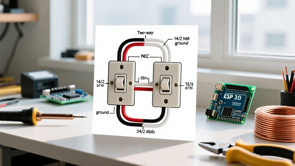
- Duplex Switch (Twin Switch): Two single-pole switches housed on a single yoke (strap). This is used to control two separate loads (e.g., a ceiling fan and a recessed light) from a single wall location. This is the most common intent behind searches for a wiring diagram for double switch configurations.
- Double-Pole Switch: A single toggle mechanism that simultaneously breaks two hot legs (L1 and L2). This is strictly used for 240V appliances like baseboard heaters or heavy-duty compressors.
This installation planning guide focuses exclusively on the standard 120V duplex switch configuration. As we navigate 2026's increasingly complex smart-home ecosystems, understanding the foundational analog wiring diagram for double switch setups is mandatory before upgrading to Wi-Fi or Zigbee-enabled alternatives.
Phase 1: Circuit Mapping and Diagnostic Preparation
The most common failure mode in switch replacements is assuming the existing wiring matches modern color-code standards. In homes built before 1980, or in rooms with previous amateur renovations, switched loops often utilize white wires as hot feeds without proper re-identification.
Essential Diagnostic Tools for 2026
Do not rely on cheap pen testers. For accurate planning, your toolkit must include:
- Non-Contact Voltage Tester (NCVT): The Klein Tools NCVT-3 (approx. $28) is the current industry standard for dual-range detection (12V to 1000V AC).
- Digital Multimeter or Solenoid Tester: The Fluke T5-1000 (approx. $185) allows you to verify the exact voltage and confirm the presence of a true neutral, which is mandatory if you plan to install smart switches later.
- Circuit Tracer: If your panel is unlabeled, a tracer like the Amprobe AT-3500 will map the breaker to the specific wall box without killing power to the whole floor.
Expert Safety Warning: Always verify your tester on a known live circuit before testing the target switch, and verify it again after confirming the target is dead. This 'Live-Dead-Live' test is mandated by OSHA and the CPSC Electrical Safety Center to prevent false-negative readings from depleted tester batteries.
Phase 2: NEC Box Fill Capacity Planning
Upgrading to a duplex switch or adding smart modules increases the physical volume of wires and devices inside the wall box. According to the NFPA 70 National Electrical Code (NEC) Article 314.16, you must calculate box fill to prevent overheating and insulation damage.
| Item in Box | 14 AWG Wire (cu. in.) | 12 AWG Wire (cu. in.) |
|---|---|---|
| Each Hot/Neutral Wire Entering | 2.0 | 2.25 |
| Ground Wires (All combined count as 1) | 2.0 | 2.25 |
| Internal Clamps (Count as 1) | 2.0 | 2.25 |
| Each Switch/Device (Counts as 2 wires) | 4.0 | 4.5 |
Planning Example: If you are installing a duplex switch on a 15-Amp circuit (14 AWG) with one incoming feed (1 hot, 1 neutral), two outgoing loads (2 hots), a shared neutral bundle, and grounds, your calculation is: 4 current-carrying wires (8.0) + 1 ground allowance (2.0) + 1 device allowance for the duplex switch (4.0) = 14.0 cubic inches minimum. A standard single-gang 18 cu. in. 'old work' box is sufficient, but a shallow 12 cu. in. box is a severe code violation.
Phase 3: The Wiring Diagram for Double Switch Configurations
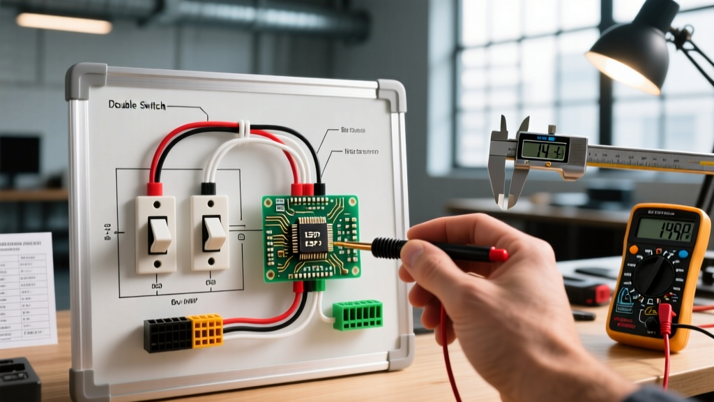
The physical wiring diagram for a standard duplex switch (such as the widely used Leviton 5622-2W Decora Duplex) hinges on understanding the break-off fins located on the side of the device.
Anatomy of the Duplex Switch
Look closely at the brass (LINE) screws and the black (LOAD) screws. Between the top and bottom screws on each side, there is a small metal connecting fin.
- LINE Side (Brass): Receives the continuous hot feed from the breaker panel.
- LOAD Side (Black): Sends the switched hot out to the light fixture or fan.
Step-by-Step Termination Sequence
Follow this exact sequence to ensure independent operation of both loads:
- Prepare the Pigtails: Cut a 6-inch piece of black wire (matching your circuit gauge, 14 or 12 AWG). Strip 3/4 inch of insulation. Use a wire nut (e.g., Ideal WireNut 72B) to connect the incoming hot feed, the pigtail, and a second 6-inch pigtail together.
- Connect the LINE Side: Attach the two pigtails to the two brass screws on the switch. Crucial Detail: Because you are using pigtails, you do not need to break the brass fin. If you were feeding the hot directly into one brass screw to power both, you would leave the fin intact. Never break the line fin unless you are feeding two entirely separate circuits (which requires a handle-tied breaker).
- Break the LOAD Fin: Using needle-nose pliers, snap off the metal fin connecting the two black LOAD screws. If you fail to do this, both switches will energize simultaneously, defeating the purpose of the duplex setup.
- Connect the Loads: Attach Load 1 (e.g., vanity light) to the top black screw. Attach Load 2 (e.g., exhaust fan) to the bottom black screw.
- Neutral and Ground: Bundle all white neutral wires together with a wire nut and push them to the back of the box (standard switches do not connect to neutral). Bundle all bare copper/green grounds, attach a pigtail to the metal box (if applicable), and secure the final pigtail to the green ground screw on the switch yoke.
Phase 4: Hardware Selection and 2026 Pricing
When sourcing materials, the choice between standard mechanical switches and smart alternatives dictates your wiring diagram requirements.
| Device Type | Model Example | Avg. Cost | Wiring Constraint |
|---|---|---|---|
| Standard Decora Duplex | Leviton 5622-2W | $4.50 - $6.00 | No neutral required. Break load fin. |
| Smart Switch (Single) | Lutron Caseta PD-5S-DV | $65.00 - $75.00 | Requires neutral. Replaces one half of a duplex. |
| Smart Relay (In-Wall) | Shelly Plus 1PM | $18.00 - $22.00 | Fits behind standard switch. Requires neutral and deep box (22+ cu in). |
Planning Note: If you intend to use smart switches in 2026, you must verify the presence of a neutral wire in the switch box. Many homes built prior to the 1990s utilized 'switch loops' where only a hot and a switched-hot were dropped to the wall box, omitting the neutral entirely. If no neutral exists, you must either pull new 14/3 or 12/3 cable from the ceiling fixture or use specialized no-neutral smart switches (like the Lutron Caseta DVRF-6L), which are significantly more expensive.
Phase 5: Edge Cases and Failure Modes
Even with a perfect wiring diagram for double switch layouts, physical installation errors cause 80% of post-installation failures. Watch for these specific edge cases:
The 'Backstabbing' Hazard
Most commercial-grade switches feature push-in 'backstab' terminals on the rear. Never use these. The internal spring-loaded grips loosen over time due to thermal expansion and contraction from the electrical load. This creates high-resistance arcing, which melts the plastic housing and causes intermittent flickering. Always use the side-binding screw terminals, wrapping the wire clockwise around the screw so that tightening the screw pulls the loop tighter.
Shared Neutral Overloading
If your double switch setup is part of a Multi-Wire Branch Circuit (MWBC)—where two separate hot legs share a single neutral wire—you must ensure the two hot breakers are on opposite phases (L1 and L2) and secured with a handle tie. If they are on the same phase, the shared neutral will carry the combined amperage of both loads, potentially exceeding the wire's thermal rating and causing a hidden wall fire.
Yoke Grounding in Metal Boxes
If you are installing the switch into a metal junction box, the switch yoke must be grounded. While the metal mounting screws provide a path, NEC 404.9(B) requires a dedicated equipment grounding conductor connected directly to the switch's green screw in most residential applications. Do not rely solely on the mounting screws for your ground path.
By thoroughly mapping your circuit, calculating your box fill, and executing the load-fin break precisely, your double switch installation will meet modern safety codes and function flawlessly for decades.