
Why Most 'Free' Wiring Diagram PDFs Fail You
When electricians, HVAC technicians, and advanced DIYers search for an electrical wiring diagram pdf free download, they are usually looking for a quick, reliable reference for wire gauges, ampacities, and National Electrical Code (NEC) color codes. Unfortunately, the internet is littered with outdated, poorly scanned, or malware-infected PDFs that reference superseded NEC articles. Relying on a 2014 diagram for a 2026 installation is a fast track to failing an inspection or causing a thermal event.
Instead of risking your safety on unverified document repositories, we have distilled the most critical data from standard wiring diagrams into this comprehensive, up-to-date reference guide. Below, you will find the exact wire gauge metrics, temperature derating rules, and color code standards mandated by the National Fire Protection Association (NFPA) 70 National Electrical Code, saving you the hassle of hunting down fragmented PDFs.
The Ultimate Wire Gauge & Ampacity Reference Table
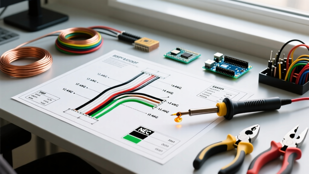
The backbone of any electrical schematic is the wire gauge. In the United States, the American Wire Gauge (AWG) system dictates the physical diameter and current-carrying capacity (ampacity) of the conductor. However, a common mistake made by those reading generic PDFs is looking only at the 90°C column for THHN/THWN-2 wire.
Expert Insight (NEC 110.14(C)): While modern THHN wire insulation is rated for 90°C, standard residential and light-commercial breakers and terminals are typically only rated for 75°C (or 60°C for circuits under 100 amps). You must size your wire based on the lowest temperature rating of any connected component, termination, or conductor in the circuit.
Standard Copper Conductor Ampacities (NEC Table 310.16)
| AWG / kcmil | Diameter (Inches) | 60°C (140°F) Ampacity | 75°C (167°F) Ampacity | 90°C (194°F) Ampacity | Common Application |
|---|---|---|---|---|---|
| 14 AWG | 0.0641 | 15 Amps | -- | 25 Amps | Lighting, standard receptacles |
| 12 AWG | 0.0808 | 20 Amps | 25 Amps | 30 Amps | Kitchen small appliance, bathroom GFCI |
| 10 AWG | 0.1019 | 30 Amps | 35 Amps | 40 Amps | Dryers, water heaters, AC units |
| 8 AWG | 0.1285 | 40 Amps | 50 Amps | 55 Amps | EV chargers (Level 2), subpanels |
| 6 AWG | 0.1620 | 55 Amps | 65 Amps | 75 Amps | 50A subpanels, large HVAC condensors |
| 4 AWG | 0.2043 | 70 Amps | 85 Amps | 95 Amps | 100A residential subpanels |
| 2 AWG | 0.2576 | 95 Amps | 115 Amps | 130 Amps | 125A service entrances, heavy feeders |
| 1/0 AWG | 0.3249 | 125 Amps | 150 Amps | 170 Amps | 150A main service panels |
| 2/0 AWG | 0.3648 | 145 Amps | 175 Amps | 195 Amps | 200A residential main service |
| 4/0 AWG | 0.4600 | 195 Amps | 230 Amps | 260 Amps | 300A-400A commercial service |
Note: Data sourced from standard engineering references and the Engineering Toolbox AWG Wire Gauge Data. Always verify local amendments to the NEC.
NEC Color Code Standards: AC, DC, and 3-Phase
Wiring diagrams use color coding to instantly communicate the function of a conductor. Misinterpreting a faded PDF diagram can lead to catastrophic cross-phasing or grounded-neutral faults. The NEC mandates specific color codes for different voltage systems, which OSHA Standard 1910.304 - Wiring design and protection strictly enforces in commercial and industrial environments.
1. Standard Single-Phase AC (120V / 240V)
- Black: Hot (Line 1) - Ungrounded conductor.
- Red: Hot (Line 2) - Ungrounded conductor (used in 240V split-phase or multi-wire branch circuits).
- White or Gray: Neutral - Grounded conductor. (Note: White tape on a black wire is permitted for larger gauge switch loops, but the reverse is strictly prohibited).
- Bare Copper or Green: Equipment Grounding Conductor (EGC).
2. Commercial 3-Phase AC Systems
For commercial panels, the voltage dictates the color code. You must label your panel directory accordingly.
| Phase | 208Y/120V System | 480Y/277V System |
|---|---|---|
| Phase A | Black | Brown |
| Phase B | Red | Orange |
| Phase C | Blue | Yellow |
| Neutral | White | Gray |
| Ground | Green, Green/Yellow Stripe, or Bare | |
3. DC Power Systems (Solar, Telecom, Automotive)
While the NEC (Article 690 for Solar) provides guidelines, the broader industry standard for DC wiring relies on distinct colors to prevent mixing up AC and DC in hybrid inverters.
- Positive (+): Red (or ungrounded positive in red).
- Negative (-): Black (or white/gray if it is the grounded conductor in a specific telecom setup, though black is standard for automotive/solar negative).
- Ground: Green or Bare.
Advanced Edge Cases: Derating and Voltage Drop
A standard wiring diagram PDF rarely accounts for the physical environment of your installation. If you simply size wire based on the base ampacity table above, you risk overheating the conductors in real-world scenarios.
Conduit Fill and Temperature Derating
When you pull more than three current-carrying conductors (CCCs) through a single raceway (conduit), the heat dissipates poorly. According to NEC Table 310.15(C)(1), you must apply a derating factor. Furthermore, if the ambient temperature in an attic exceeds 86°F (30°C), you must apply a temperature correction factor.
Real-World Example: You are running a multi-wire branch circuit (MWBC) and two standard 120V circuits in the same 3/4-inch EMT conduit. That equals 4 current-carrying conductors (the neutrals on the MWBC cancel out, but the two individual circuit neutrals count).
- Base wire: 12 AWG THHN (90°C column = 30 Amps).
- 4 CCCs require an 80% derating factor.
- 30A x 0.80 = 24 Amps.
- Because 24A is still higher than the 20A breaker limit, 12 AWG is safe. However, if you added two more circuits (8 CCCs, 70% derating), 30A x 0.70 = 21A. You are now dangerously close to the limit and must upsize to 10 AWG to maintain safety margins and comply with termination rules.
Voltage Drop: The Hidden Diagram Killer
The NEC recommends (but does not strictly mandate for most branch circuits) a maximum voltage drop of 3% for branch circuits and 5% total for feeder + branch. If your wiring diagram shows a 12 AWG wire running 150 feet to a 15A well pump, the math dictates a failure:
- Formula: VD = (2 x K x I x D) / CM
- K (Copper resistance) = 12.9
- I (Current) = 15A
- D (Distance) = 150 ft
- CM (Circular Mils for 12 AWG) = 6530
- Result: (2 x 12.9 x 15 x 150) / 6530 = 8.89 Volts Dropped.
On a 120V circuit, 8.89V is a 7.4% drop. The pump motor will overheat and fail prematurely. You must upsize to 8 AWG for this run, a detail a generic PDF diagram will never explicitly tell you.
Where to Safely Download Legitimate Electrical Diagrams
If you still require full schematic PDFs for specific panels, motor starters, or HVAC control boards, avoid random forum attachments. Instead, source your electrical wiring diagram pdf free download directly from the manufacturers or authoritative bodies:
- Schneider Electric / Square D: Their official wiring diagram portal provides verified, up-to-date PDFs for all Digipact, PowerPact, and QO/Homeline load centers.
- Mike Holt Enterprises: Offers incredible free resources, including NEC code change summaries and illustrated diagram PDFs that explain the 'why' behind the code.
- Manufacturer Spec Sheets: For appliances (like Trane HVAC units or Generac transfer switches), always locate the physical wiring diagram glued inside the unit's access panel. If it is missing, download the exact model number's service manual from the OEM's official support site.
Summary: Code Over Convenience
While finding an electrical wiring diagram PDF free download is a great starting point for understanding circuit topology, it is not a substitute for knowing the National Electrical Code. Wire gauges must be selected based on termination temperatures, ambient heat, conduit fill, and voltage drop. Color codes must strictly follow the voltage system in use to protect future technicians. Always cross-reference your downloaded diagrams with the latest adopted NEC cycle in your local municipality to ensure a safe, code-compliant installation.