
Decoding the Appliance Wiring Diagram for Home Circuits
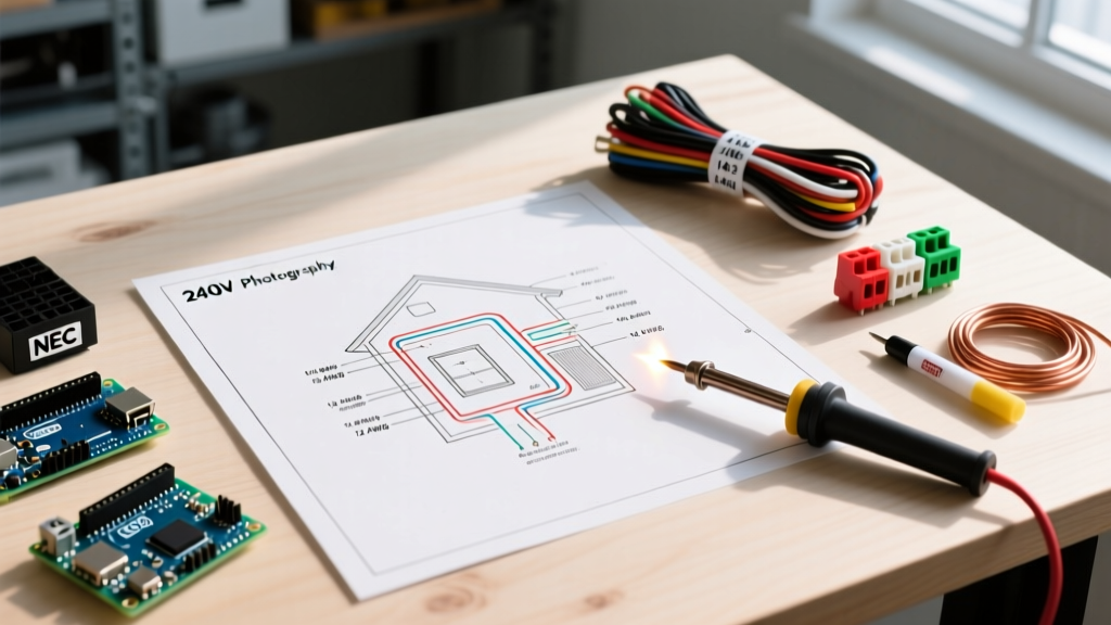
When you pull up a wiring diagram for home appliance circuits, you are looking at the critical bridge between your electrical panel and high-draw machinery. Unlike standard 120V lighting or receptacle circuits, 240V appliance circuits—used for electric ranges, clothes dryers, and Level 2 EV chargers—demand strict adherence to the National Electrical Code (NEC). A misread symbol or an undersized wire on a 240V diagram doesn't just trip a breaker; it creates a severe thermal runaway hazard. According to the National Fire Protection Association (NFPA), electrical distribution and lighting equipment are consistently among the top causes of home structure fires. This tutorial breaks down how to read, interpret, and execute a 240V appliance wiring diagram with professional-grade precision.
The Core Symbols in 240V Diagrams
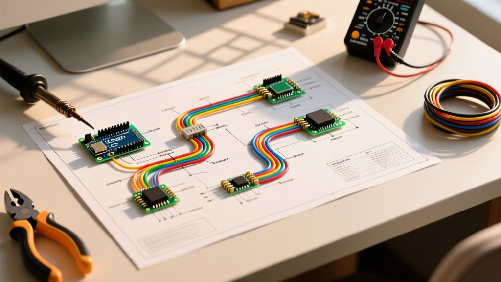
Before stripping a single wire, you must understand the schematic language. Most appliance wiring diagrams utilize standard NEMA (National Electrical Manufacturers Association) and IEEE symbols. Here is what you will encounter:
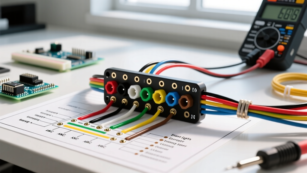
- L1 and L2 (Hot Legs): Represent the two 120V ungrounded conductors. Together, they provide 240V. On a diagram, these are typically black and red lines.
- N (Neutral): The grounded conductor (white or gray). In pure 240V appliances (like baseboard heaters), this is omitted. In 120/240V appliances (like ranges and dryers), it carries the 120V return current for control boards and timers.
- G or PE (Protective Earth): The equipment grounding conductor (bare copper or green). This is your safety fault path.
- Double-Pole Breaker Symbol: Shown as two linked toggles, indicating a common trip mechanism that disconnects both L1 and L2 simultaneously.
The 3-Wire vs. 4-Wire Paradigm Shift
If you are consulting a wiring diagram for home retrofits in older properties, you will inevitably run into the 3-wire vs. 4-wire dilemma. Prior to the 1996 NEC revision, ranges and dryers were wired using a 3-wire setup (two hots and a neutral). The appliance frame was bonded directly to the neutral wire. This created a lethal edge case: if the neutral wire broke or developed high resistance, the 120V return current would energize the metal chassis of the dryer or range.
Modern diagrams strictly mandate a 4-wire configuration (NEMA 14-30 for dryers, NEMA 14-50 for ranges/EV chargers). The neutral and ground are kept entirely separate at the receptacle, isolating the chassis from any current-carrying conductors. If your home still has 3-wire NEMA 10-30 or 10-50 receptacles, the only code-compliant solution in 2026 is to run a new 4-wire circuit from the panel.
Wire Gauge and Breaker Sizing Matrix
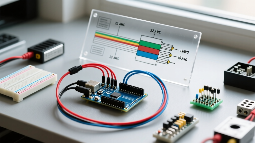
A wiring diagram is only as good as the load calculations supporting it. The NEC distinguishes between continuous loads (operating for 3 hours or more) and non-continuous loads. This distinction drastically alters your wire gauge and breaker sizing.
| Appliance Type | NEMA Receptacle | Max Amperage | Wire Gauge (Copper NM-B) | Breaker Size | Load Classification |
|---|---|---|---|---|---|
| Electric Clothes Dryer | 14-30R | 30A | 10 AWG (10/3 with ground) | 30A Double-Pole | Non-Continuous |
| Electric Range / Oven | 14-50R | 50A | 6 AWG (6/3 with ground) | 50A Double-Pole | Non-Continuous |
| Level 2 EV Charger (32A) | 14-50R | 40A (Continuous) | 6 AWG (6/3 NM-B or THHN) | 50A Double-Pole | Continuous (125% Rule) |
| Level 2 EV Charger (48A) | Hardwired | 60A (Continuous) | 4 AWG (4/2 NM-B or THHN) | 60A Double-Pole | Continuous (125% Rule) |
The 125% Continuous Load Rule: Under NEC Article 210.20(A), if an EV charger draws 40 amps continuously, the circuit must be rated for 125% of that load (40 x 1.25 = 50 amps). You cannot install a 40A continuous load on a 40A breaker; it will eventually cause thermal degradation and nuisance tripping.
Step-by-Step: Wiring a NEMA 14-50 Receptacle
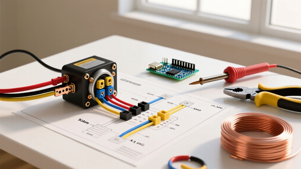
The NEMA 14-50 is the undisputed king of 240V home appliance diagrams, serving both heavy kitchen ranges and high-speed EV chargers. However, the physical execution of this diagram requires specific attention to torque and thermal management.
1. Panel Termination and Conduit Fill
Begin at the main service panel. Install a 50A double-pole breaker. If you are using 6/3 NM-B (Romex), ensure the cable is secured within 12 inches of the panel. If you are pulling individual THHN wires through EMT conduit, remember that conduit fill capacity limits how many current-carrying conductors can share a pipe without requiring ampacity derating.
2. Receptacle Selection: The Thermal Trap
Not all NEMA 14-50 receptacles are built equally. For electric ranges that cycle on and off, a standard $15 residential receptacle (like the basic Leviton 279-S00) is generally sufficient. However, if your wiring diagram for home EV charging specifies a 14-50 outlet, do not use standard residential receptacles. Continuous 40A draws cause cheap brass contacts to expand, lose tension, and arc, leading to melted faceplates and fires. Upgrade to a commercial-grade receptacle like the Hubbell 9450A or Bryant 9450FR (typically priced around $85-$110 in 2026), which feature massive, high-tension contact blades designed for continuous thermal loads.
3. Torque Specifications (NEC 110.14)
Since the 2017 NEC cycle, and strictly enforced in 2026, electricians must use a calibrated torque screwdriver to terminate connections. The Hubbell 9450A requires exactly 75 inch-pounds of torque on its terminal screws. Hand-tightening is no longer code-compliant and is the leading cause of high-resistance connection failures in 240V appliance circuits.
Troubleshooting Common Diagram Misreads
Even with a clear schematic, field conditions introduce variables that can derail an installation. Here are the most common failure modes when executing a 240V appliance wiring diagram:
- Reversed Neutral and Ground: On a NEMA 14-50, the neutral is the straight vertical blade, while the ground is the U-shaped pin. Swapping these at the receptacle will cause the appliance chassis to carry return current, creating a severe shock hazard and tripping GFCI/AFCI protection if installed upstream.
- Shared Neutrals on MWBCs: If your diagram incorporates a Multi-Wire Branch Circuit (MWBC) to feed 120V appliance controls, ensure the two hot legs are on opposite phases (measuring 240V between them). If they are on the same phase, the shared neutral will carry the sum of the currents instead of the difference, resulting in an immediate neutral wire overload and potential fire.
- Voltage Drop Over Distance: Standard wire gauge charts assume runs under 100 feet. If your panel is 150 feet away from your new EV charger or workshop welder, you must upsizing your wire by one gauge (e.g., from 6 AWG to 4 AWG) to keep voltage drop below the NEC-recommended 3% threshold for optimal appliance performance.
Safety and Code Compliance
Working with 240V circuits leaves zero margin for error. Always verify that the main breaker is off and use a non-contact voltage tester alongside a digital multimeter to confirm zero potential before touching any bus bars. Furthermore, the Electrical Safety Foundation International (ESFI) strongly recommends that any panel modifications or new 240V circuit runs be permitted and inspected by your local Authority Having Jurisdiction (AHJ). For comprehensive guidelines on home energy upgrades and high-draw appliance installations, the U.S. Department of Energy provides excellent resources on load management and panel capacity assessments.
Mastering the wiring diagram for home appliance circuits is about more than just matching colors to terminals. It requires an understanding of continuous load mathematics, thermal dynamics of receptacle materials, and strict adherence to modern torque specifications. By treating every 240V installation with the rigor of a commercial project, you ensure your home's high-draw appliances operate safely and efficiently for decades.