
Strategic Planning for Modern Garage Power Systems
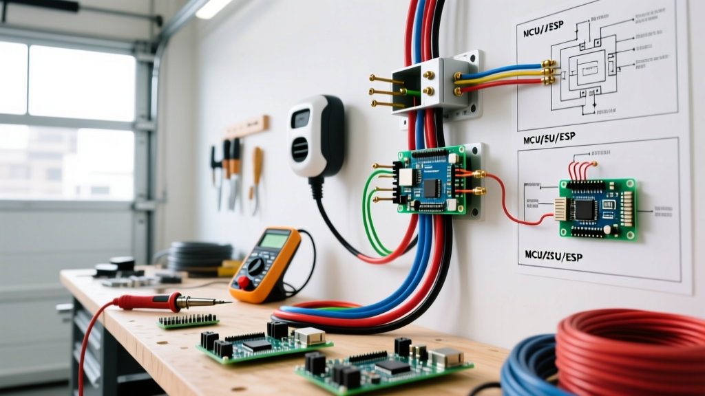
Designing accurate garage electrical wiring diagrams requires moving beyond basic residential lighting plans. In 2026, the modern garage functions as a high-demand workshop, an EV charging station, and a climate-controlled storage space. A generic 15-amp lighting circuit and a single duplex receptacle will immediately trip breakers when running an air compressor alongside a MIG welder. Proper installation planning demands a zoned approach, strict adherence to the latest National Electrical Code (NEC), and precise load calculations to prevent voltage drop and thermal failures.
This guide provides the technical framework for mapping your garage circuits, selecting the correct wire gauges, and designing a subpanel feed that accommodates both current tools and future heavy-load upgrades.
Core NEC Requirements for Garage Installations
Before drafting your diagram, you must integrate the mandatory safety baseline dictated by the National Fire Protection Association (NFPA). The NEC strictly regulates garage environments due to the presence of combustible vapors, dust, and heavy inductive loads.
- GFCI Protection (NEC 210.8(A)(2)): All 125-volt and 250-volt receptacles rated 15 to 50 amps in a garage must have Ground-Fault Circuit Interrupter (GFCI) protection. This includes dedicated appliance receptacles and EV charging outlets.
- Receptacle Spacing (NEC 210.52(G)): At least one receptacle outlet must be installed in each attached garage, and at least one in each detached garage with electric power. However, practical workshop planning dictates placing 20-amp receptacles every 6 to 8 feet along workbenches.
- Lighting Restrictions: Fluorescent or LED fixtures installed in garages where vehicles are parked must be physically protected or rated for impact resistance to prevent shattering if struck by a ladder or cargo.
Expert Insight: Do not rely on GFCI breakers in the main panel for long garage runs. High capacitance in long wire runs can cause nuisance tripping. Instead, use standard breakers in the panel and install GFCI receptacles (like the Leviton 2091-GY) at the point of use or as the first device in the daisy chain.
Zoning Your Garage Electrical Wiring Diagrams
Effective diagrams divide the garage into distinct power zones. This prevents a high-inrush current tool (like an air compressor) from causing a voltage sag that damages sensitive electronics (like a CNC router or EV charger logic board) on the same circuit.
Circuit Allocation Matrix
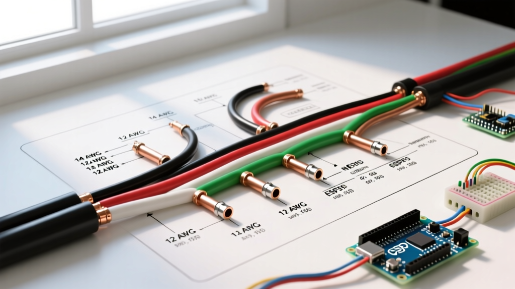
Use the following matrix as the foundation for your wiring diagram. All wire gauges assume copper THHN/THWN-2 in conduit or standard NM-B (Romex) for indoor dry locations.
| Zone / Appliance Target | Breaker Size | Wire Gauge (Copper) | Receptacle / Disconnect |
|---|---|---|---|
| General LED Lighting | 15A | 14 AWG | Standard Toggle / Smart Relay |
| Workbench General Tools | 20A | 12 AWG | NEMA 5-20R (GFCI protected) |
| Air Compressor (e.g., California Air Tools 10020C) | 20A Dedicated | 12 AWG | NEMA 5-20R |
| Dust Collection System (1.5 HP - 3 HP) | 20A Dedicated | 12 AWG | NEMA 5-20R or Twist-Lock L5-20 |
| Level 2 EV Charger (e.g., ChargePoint Home Flex) | 50A Dedicated | 6 AWG | NEMA 14-50R or Hardwired |
| MIG/TIG Welder (240V Input) | 50A Dedicated | 6 AWG | NEMA 6-50R |
Heavy-Duty Loads: EV Chargers and Welders
The most critical aspect of modern garage wiring diagrams is accommodating 240-volt continuous and intermittent heavy loads. According to the U.S. Department of Energy Alternative Fuels Data Center, Level 2 home charging is the standard for daily EV replenishment, requiring dedicated infrastructure.
The 125% Continuous Load Rule
EV chargers are classified as continuous loads (operating for 3 hours or more). Under NEC Article 210.20(A), the branch circuit must be rated at 125% of the continuous load.
Example: If you install a 40-amp EV charger, the math dictates 40A x 1.25 = 50A. Therefore, your diagram must specify a 50-amp breaker (such as a Square D Q250) and #6 AWG copper wire. Never put a 40-amp continuous load on a 40-amp breaker; it will eventually overheat and trip the thermal protection.
Welder Receptacle Nuances
Welders operate under NEC Article 630, which allows for specific duty-cycle calculations. However, for a multi-purpose garage diagram, planning a 50-amp circuit with a NEMA 6-50R receptacle using #6 AWG wire provides the flexibility to run anything from a 140-amp hobbyist MIG to a 210-amp professional TIG welder without rewiring.
Subpanel Sizing and Feed Diagrams for Detached Garages
If your garage is detached, or if your main home panel lacks the physical spaces for 6+ new double-pole and single-pole breakers, your diagram must include a subpanel. A 100-amp subpanel (like the Square D HOM48L125PGC, retailing around $180-$220 in 2026) is the minimum recommended size for a fully equipped workshop.
Feeder Cable and Trenching Specifications
For a 100-amp feed to a detached garage, use 2-2-2-4 Aluminum MH feeder cable (rated for 90 amps, but universally accepted for 100A residential subpanels under specific NEC 310.12 dwelling service allowances, or upgrade to 1/1/1/3 AL for a strict 100A rating).
Trenching Depth: NEC Table 300.5 mandates that PVC conduit containing residential branch circuits and feeders must be buried at least 18 inches deep. Where the conduit emerges from the ground, it must transition to Schedule 80 PVC or rigid metal conduit up to 8 feet to protect against physical damage from vehicles or landscaping equipment.
The 4-Wire Feed and Grounding Electrode System
Your subpanel diagram must explicitly show a 4-wire feed: two hot legs, one neutral, and one equipment grounding conductor.
Critical Edge Case: In a subpanel, the neutral bar and the ground bar must remain isolated. Remove the green main bonding screw from the subpanel's neutral bar. Failure to do this creates a parallel neutral path, energizing the grounding system and posing a lethal shock hazard.
Additionally, a detached garage requires its own Grounding Electrode System (NEC 250.32). Your diagram should detail two 8-foot copper ground rods, spaced at least 6 feet apart, driven into the earth and connected to the subpanel ground bar using #6 AWG bare copper wire.
Voltage Drop: The Hidden Failure Mode
Many DIY garage diagrams fail to account for distance. The NEC recommends a maximum voltage drop of 3% for branch circuits and 5% overall. If your detached garage is 150 feet from the main panel, standard #6 AWG wire on a 50-amp EV circuit will experience a voltage drop exceeding 4%, causing the charger to throttle amperage or overheat the wire insulation over time.
The Solution: For runs exceeding 100 feet on 50-amp circuits, your diagram must specify upsizing the wire to #4 AWG copper. While this increases material costs by approximately $2.50 per foot, it ensures the EV charger receives a stable 240V, maximizing charging speed and preventing thermal degradation of the conductors.
Finalizing Your Blueprint
When drawing your final garage electrical wiring diagrams, use distinct color codes: red for 240V hot lines, black for 120V hot lines, white for neutrals, and green/bare for grounds. Label every junction box, specify the exact NEMA receptacle configurations, and include a legend detailing the torque specifications for all breaker lugs (typically 35-50 in-lbs for standard residential breakers). Precision in the planning phase eliminates the most common cause of garage electrical fires: loose, high-resistance connections born from rushed installations.