
Understanding the Electric Baseboard Heating Wiring Diagram
Electric baseboard heaters are purely resistive loads, meaning they convert 100% of the electrical current passing through them into heat. While their internal construction is simple—essentially a long nichrome or kanthal wire wrapped in aluminum fins—their integration into a home's electrical panel requires strict adherence to the National Electrical Code (NEC), specifically Article 424 (Fixed Electric Space-Heating Equipment). Whether you are installing a single 4-foot unit in a bathroom or daisy-chaining three 6-foot units in a basement, interpreting the electric baseboard heating wiring diagram correctly is critical for fire safety and optimal performance.
This guide breaks down the exact wiring topologies for both 120V and 240V configurations, explores the nuances of line-voltage versus low-voltage smart thermostat integration, and provides the precise wire gauge and breaker sizing matrices required for modern installations.
The Core Circuit Path: Panel to Element
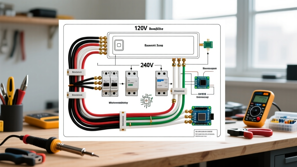
Before examining specific thermostat configurations, you must understand the fundamental current path. Unlike motorized appliances that require a neutral return path, standard 240V electric baseboard heaters (such as the popular Cadet F Series or Marley Qmark models) operate on a dual-hot leg system.
- The Source: Power originates at a dedicated double-pole circuit breaker in the main service panel.
- The Switching Point: The current travels through the wall-mounted thermostat, which acts as a variable resistor or a simple mechanical contactor to interrupt the hot leg(s).
- The Load: Current enters the heater's junction box, passes through the high-limit thermal cutoff switch (a critical safety device that trips if the element exceeds 194°F / 90°C), and finally energizes the resistive element.
Critical Safety Note: In a 240V circuit, the white wire in a standard 12/2 NM-B (Romex) cable is not a neutral. It is a second hot leg. NEC 200.7(C) requires you to re-identify this white wire with black or red electrical tape at both the panel and the heater junction box to indicate it is carrying line voltage.
120V vs. 240V Wiring Matrix and Sizing
Choosing between 120V and 240V dictates your wire gauge, breaker size, and the maximum physical length of the baseboard heater you can install on a single circuit. According to the U.S. Department of Energy, 240V systems are vastly preferred for whole-room heating because they draw half the amperage for the same wattage output, reducing voltage drop and allowing for longer, higher-capacity units.
| System Voltage | Breaker Size | Wire Gauge (NM-B) | Max Continuous Load (125% Rule) | Max Wattage Capacity | Approx. Max Heater Length |
|---|---|---|---|---|---|
| 120V | 15 Amp (Single Pole) | 14 AWG | 12 Amps | 1,440 Watts | 3 to 4 feet |
| 120V | 20 Amp (Single Pole) | 12 AWG | 16 Amps | 1,920 Watts | 4 to 5 feet |
| 240V | 20 Amp (Double Pole) | 12 AWG | 16 Amps | 3,840 Watts | 8 feet |
| 240V | 30 Amp (Double Pole) | 10 AWG | 24 Amps | 5,760 Watts | 12 feet (or multiple daisy-chained) |
Note: Heating loads are considered continuous by the NEC (operating for 3 hours or more). Therefore, a 20A breaker can only safely carry 16A of continuous heating load (20 x 0.80 = 16A).
Thermostat Wiring: Line-Voltage vs. Low-Voltage Smart Relays
The most complex part of any electric baseboard heating wiring diagram is the thermostat integration. You have two primary architectural choices: traditional line-voltage thermostats or modern low-voltage smart thermostats utilizing an isolation relay.
1. Line-Voltage Thermostats (Single-Pole vs. Double-Pole)
Line-voltage thermostats (like the Honeywell CT410B or Cadet B-Mech) are wired directly in series with the heater element. They handle the full 120V or 240V current.
- Single-Pole Wiring: The thermostat breaks only one of the hot legs. The heater element remains energized with 120V (in a 240V system) even when turned 'off'. While it won't produce heat due to the broken circuit, touching the internal element can still result in a fatal shock. Single-pole thermostats usually have a 'low' setting rather than a true 'off' position.
- Double-Pole Wiring: The thermostat breaks both hot legs simultaneously. This provides a true 'off' state and isolates the heater completely from the panel. Many local jurisdictions mandate double-pole thermostats for 240V baseboards for this exact safety reason.
2. Low-Voltage Smart Thermostats (The Relay Method)
Standard smart thermostats (Nest, Ecobee) operate on 24V AC and cannot handle 240V line voltage. To integrate them, you must use a heavy-duty switching relay, such as the Aube TI840-01 or the White-Rodgers 586-902.
- The Line Voltage Side: Wire the 240V supply from the breaker into the relay's 'Line' terminals (L1 and L2). Wire the 'Load' terminals (T1 and T2) directly to the baseboard heater's junction box.
- The Low Voltage Side: The Aube TI840 features a built-in 24V transformer. Wire the 'R' (Power) and 'W' (Heat Call) terminals from your smart thermostat to the corresponding 24V terminals on the relay.
- The Logic: When the smart thermostat calls for heat, it closes the 24V circuit. This energizes the relay's internal coil, which physically pulls the heavy-duty contacts closed, allowing 240V to flow to the baseboard heater.
Daisy-Chaining Multiple Heaters on One Circuit
If you are heating a large space, you may need to wire multiple baseboard units to a single 30A, 240V breaker. According to Cadet Heat installation guidelines, multiple heaters must always be wired in parallel, never in series. Wiring in series divides the voltage across the units, resulting in severely diminished heat output and potential element failure.
Box Fill Calculations and Junction Sizing
When daisy-chaining, the junction box of the first heater acts as a pass-through point. This triggers NEC Article 314.16 regarding box fill capacity. A standard baseboard junction box is often too small to accommodate the incoming 10/2 NM-B cable, the outgoing 10/2 NM-B cable, and the internal element pigtails.
- The Fix: Install an external 4x4x2.125 inch steel or high-heat rated plastic junction box adjacent to the heater.
- Wire Nuts: Use high-temperature ceramic wire nuts or copper crimp sleeves with heat-shrink tubing for the pass-through connections. Standard vinyl wire nuts can melt and fail when subjected to the ambient heat radiating from the baseboard fins.
- Torque Specifications: When terminating wires at the heater's internal terminal block, use a torque screwdriver set to 12-14 in-lbs (verify with the specific manufacturer's spec sheet). Under-torqued connections create micro-arcing, leading to melted terminal blocks and fire hazards.
Common Failure Modes and Troubleshooting
Even with a perfect electric baseboard heating wiring diagram, environmental factors and installation errors can cause system failures. Here is how to diagnose the most common issues:
The Breaker Trips Immediately Upon Energizing
This is almost always a dead short. The most common culprit is the high-limit thermal switch inside the heater junction box. If the wires were stripped too far back during installation, a stray strand of copper may be touching the grounded metal chassis of the heater. Disconnect power, remove the junction box cover, and inspect for ground faults using a multimeter in continuity mode.
The Heater Hums or Clicks Repeatedly
A loud humming noise usually indicates a failing mechanical thermostat contact. The internal bimetallic strip is chattering as it struggles to maintain the connection under heavy amperage. Replace the line-voltage thermostat. If the clicking is coming from the heater itself, the element may be expanding and contracting against a tight mounting bracket. Loosen the wall-mounting screws by a quarter-turn to allow for thermal expansion.
Uneven Heating (One End is Cold)
Baseboard heaters rely on natural convection. If the cold air intake at the bottom or the hot air exhaust at the top is obstructed by carpet, dust bunnies, or heavy drapes, the internal temperature will spike, tripping the high-limit switch prematurely. Ensure a strict 12-inch clearance in front of the unit and maintain a 1/2 inch gap between the floor and the bottom of the heater casing to allow proper airflow.
Final Inspection Checklist
Before closing up junction boxes and turning on the main breaker, verify the following:
- White wires used as hot legs in 240V circuits are re-identified with black/red tape.
- All ground wires (bare copper) are bonded to the metal junction boxes using a green grounding screw or grounding clip.
- The circuit breaker matches the continuous load calculation (Wattage / Voltage = Amps; Amps x 1.25 = Minimum Breaker Size).
- No insulation is touching the heater element or the back of the junction box.
By strictly following these wiring diagrams and NEC guidelines, your electric baseboard heating system will provide decades of silent, maintenance-free supplemental heat.