
When searching for a wiring diagram for subwoofer and amp installations, most online guides focus purely on making the system play loud. However, ignoring 12V electrical codes and mobile safety standards is a leading cause of vehicle fires, alternator failures, and catastrophic amplifier damage. A high-output audio system is essentially a high-current electrical circuit; treating it like a simple plug-and-play accessory is a critical mistake.
In 2026, with the rise of high-draw Class D amplifiers and aftermarket Lithium Iron Phosphate (LiFePO4) 12V batteries, adhering to strict safety protocols is non-negotiable. This guide provides a comprehensive, code-compliant wiring diagram for subwoofer and amp configurations, grounded in the standards set by the Mobile Electronics Certification Program (MECP) and marine-grade safety protocols.
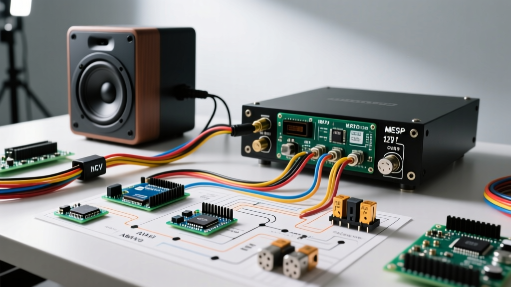
The MECP & ABYC Compliant Wiring Diagram for Subwoofer and Amp
Whether you are wiring a daily-driven truck or a marine vessel, the fundamental physics of 12V DC power remain the same. The American Boat & Yacht Council (ABYC) E-11 standard for marine DC electrical systems and MECP automotive guidelines dictate strict rules for wire sizing, overcurrent protection, and routing. Below is the step-by-step execution of a safe, high-fidelity installation.
Step 1: Power Wire Sizing and the 18-Inch Fusing Rule
The most severe code violation in mobile audio is placing the main power fuse too far from the battery. According to MECP and ABYC standards, the main overcurrent protection device (fuse or circuit breaker) must be installed within 18 inches of the positive battery terminal. This protects the entire length of the power cable in the event of a short circuit to the vehicle chassis.
- Amplifier Example: JL Audio HD1200/1 (Class D, ~100A max draw at 12.5V).
- Wire Selection: 1/0 AWG Oxygen-Free Copper (OFC). Never use Copper-Clad Aluminum (CCA) for high-current runs; CCA has 40% higher resistance and is a known fire hazard under sustained high loads.
- Overcurrent Protection: 120A ANL fuse for standard Lead-Acid/AGM batteries. If using a LiFePO4 battery with a high-discharge BMS, you must upgrade to a Class T fuse due to the battery's massive short-circuit current capacity, which can melt standard ANL elements before they clear the fault.
Step 2: The Grounding Protocol (Avoiding Ground Loops)
A poor ground does not just cause your amplifier to shut off; it forces the amp to draw current through the RCA shields, resulting in severe alternator whine and potential preamp stage burnout.
- Locate Chassis Metal: Find a structural bolt on the vehicle chassis within 3 feet of the amplifier.
- Surface Prep: Use a 60-grit sanding disc to remove all paint, primer, and rust down to bare, shiny metal. The contact area must be slightly larger than the ring terminal.
- Corrosion Protection: After securing the 1/0 AWG ground ring terminal (torqued to 40 in-lbs), coat the exposed bare metal with a dielectric grease or dedicated battery terminal protector to prevent galvanic corrosion.
- Verification: Use a digital multimeter (DMM) to measure resistance between the amplifier's ground terminal and the battery's negative post. It must read less than 0.05 ohms.
Step 3: Remote Turn-On and RCA Signal Routing
Electromagnetic Interference (EMI) from the vehicle's wiring harness and the amplifier's power cable will induce noise into unbalanced RCA cables.
Pro Routing Rule: Run your 12V power cable down the driver's side of the vehicle, and your RCA signal cables and remote turn-on wire down the passenger side. Maintain a minimum separation of 18 inches between power and signal wires whenever they must cross the vehicle's center console or firewall.
For the remote turn-on wire, do not tap into high-current circuits like the fuel pump or ignition coil. Use a low-current accessory circuit, or utilize a PAC TRUNK-LOC or similar line-output converter with a dedicated 12V remote output to prevent back-feeding voltage into sensitive vehicle CAN-bus modules.
AWG Wire Size vs. Amperage & Distance Matrix
Voltage drop is the silent killer of subwoofer amplifiers. When an amplifier experiences voltage sag below 11.5V, its internal power supply works harder, generating excess heat and clipping the audio signal, which rapidly destroys subwoofer voice coils. Use the matrix below to select the correct OFC wire gauge based on your total system amperage and cable length.
| Max System Draw (Amps) | 0 - 10 Feet | 10 - 15 Feet | 15 - 20 Feet | 20+ Feet (Marine/SUV) |
|---|---|---|---|---|
| 0 - 40A | 8 AWG | 8 AWG | 6 AWG | 4 AWG |
| 40 - 80A | 4 AWG | 4 AWG | 2 AWG | 1/0 AWG |
| 80 - 120A | 2 AWG | 1/0 AWG | 1/0 AWG | 2/0 AWG |
| 120 - 180A | 1/0 AWG | 1/0 AWG | 2/0 AWG | 3/0 AWG |
| 180 - 250A+ | 2/0 AWG | 2/0 AWG | 3/0 AWG | 4/0 AWG |
Note: Calculations assume a maximum allowable voltage drop of 0.5V (approx 4%) at 12.5V nominal, utilizing true stranded OFC wire at 105°C rating.
Component Selection: 2026 Market Pricing & Specs
Building a reliable system requires matching components correctly. Here is a benchmark setup for a high-output, code-compliant daily driver:
- Amplifier: JL Audio HD1200/1 ($899) - Ultra-compact Class D, features onboard voltage monitoring and thermal rollback protection.
- Subwoofer: Kicker L7T 12-Inch ($349) - Shallow mount, 2-ohm DVC, handles 600W RMS. Requires a sealed enclosure of 0.8 to 1.2 cubic feet for optimal transient response.
- Wiring Kit: Stinger True-Spec 1/0 AWG OFC Kit ($189) - Includes true AWG wiring, Tinned copper ring terminals, and a high-quality ANL fuse holder.
- Total Hardware Cost: ~$1,437 (excluding custom fabrication and labor).
2026 Safety Alert: LiFePO4 Battery Integrations
The mobile audio landscape has shifted dramatically toward 12V Lithium Iron Phosphate (LiFePO4) batteries to supplement alternator output. While these batteries maintain a resting voltage of 13.8V to 14.2V (eliminating voltage sag and headlight dimming), they introduce severe safety risks if wired incorrectly.
According to guidelines referenced by the National Fire Protection Association (NFPA) regarding lithium energy storage, a lithium battery can deliver 5 to 10 times the short-circuit current of a lead-acid battery. A standard ANL fuse may arc and sustain a plasma fire before blowing under a direct lithium short. You must use a Class T fuse or a high-interrupt-capacity (AIC) marine circuit breaker when wiring a lithium 12V bank to an audio amplifier distribution block.
Troubleshooting Code Violations & Failure Modes
Failure Mode 1: Thermal Runaway and Clipping
Symptom: Subwoofer voice coil melts or amplifier shuts down with a red thermal LED after 20 minutes of play.
Root Cause: Undersized power wire causing voltage drop. The amp's internal DC-DC converter draws excessive amperage to compensate for low input voltage, overheating the power supply toroids.
Fix: Upgrade from 4 AWG CCA to 1/0 AWG OFC and verify alternator output under load (should remain above 13.5V).
Failure Mode 2: Alternator Whine (Ground Loop)
Symptom: High-pitched whine that increases in pitch with engine RPM.
Root Cause: The amplifier ground and the head unit ground are at different electrical potentials. Current flows through the RCA shields to equalize the potential.
Fix: Do not use ground loop isolators (they destroy audio bandwidth). Instead, re-verify the head unit chassis ground and ensure the amplifier ground is sanded to bare chassis metal with <0.05 ohms of resistance to the battery negative.
Frequently Asked Questions (FAQ)
Can I use the vehicle's seatbelt bolt for my amplifier ground?
No. While seatbelt bolts are anchored to the chassis, they often utilize thread-locking compounds or isolation washers that increase resistance. Furthermore, drawing 100A+ through a structural safety point can compromise the bolt's integrity in a collision. Always use a dedicated, non-structural chassis bolt.
Do I need a capacitor for my subwoofer and amp wiring?
In 2026, stiffening capacitors are largely considered obsolete for high-draw systems. They charge too slowly to assist with dynamic bass transients and can actually mask voltage drops, preventing your amplifier's internal protection circuits from triggering. A high-output alternator (e.g., Mechman 320A) or a supplementary LiFePO4 battery is the code-compliant solution for voltage stabilization.
What size fuse do I need at the amplifier if I already have one at the battery?
The battery fuse protects the wire. If you are using a distribution block to feed multiple amplifiers, you must place a secondary fuse at the distribution block or at each amplifier's inline holder, rated specifically for that amplifier's maximum draw plus 10%. For a 100A amp, use a 110A ANL or AGU fuse at the amp location.