
Decoding the Standard Wiring Diagram for Ceiling Fan with Light and Remote
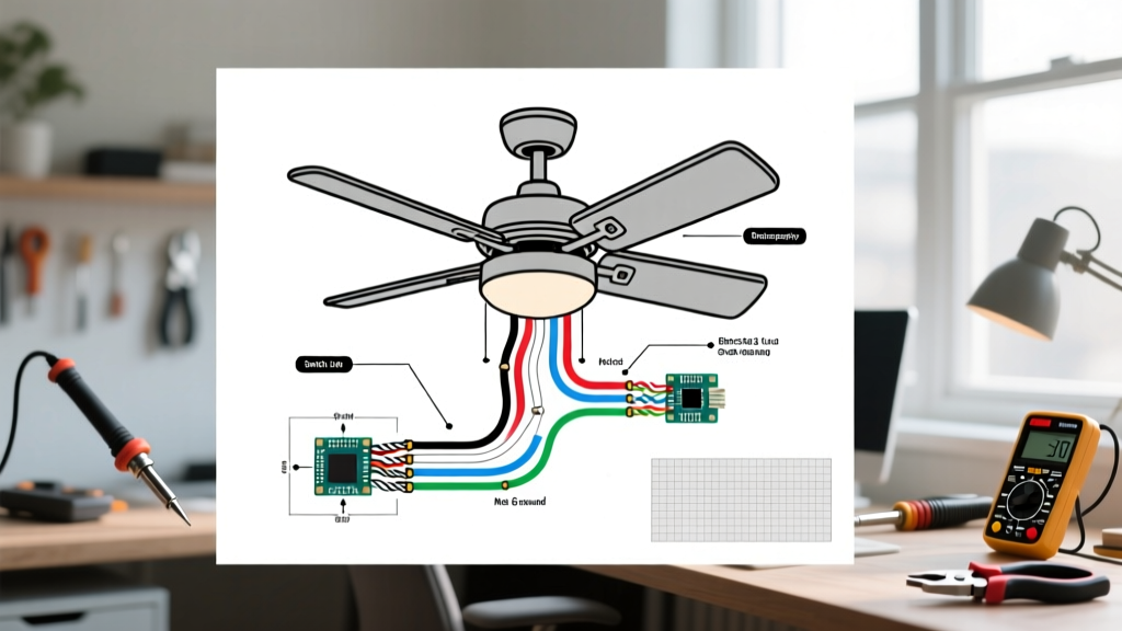
In modern residential electrical work, ceiling fans equipped with integrated lighting and RF (radio frequency) remote controls are ubiquitous. While they offer excellent convenience, the addition of a canopy-mounted receiver module introduces a notorious failure point. When your fan stops responding, the wiring diagram for ceiling fan with light and remote configurations becomes your primary diagnostic map. Unlike standard hardwired fans, remote-controlled models require you to trace voltage through an intermediary 'brain' before it reaches the motor or light kit.
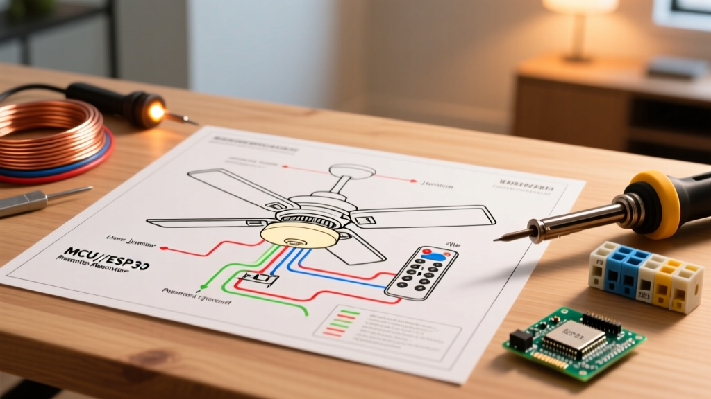
Before opening the canopy, it is critical to understand the standard color codes dictated by the National Electrical Code (NEC). In a typical 2026 residential setup, your ceiling junction box will supply a black (hot), white (neutral), and bare/green (ground) wire. The remote receiver module—such as the widely used Hunter 99119 or Hampton Bay UC7080T—acts as a bridge. It takes the raw AC line voltage and distributes it via internal relays to the fan motor (black output) and the light kit (blue output).
The Canopy Receiver: Where Diagrams Meet Reality
The most common point of failure in any remote-controlled ceiling fan is the receiver module hidden inside the canopy. Because these units are crammed into a confined space alongside wire nuts and mounting brackets, heat dissipation is poor. Over time, the internal capacitors and TRIACs degrade. When troubleshooting, you must isolate whether the failure is upstream (house wiring), at the receiver (the module itself), or downstream (the fan motor/light kit).
Critical Warning: The Dimmer Switch Catastrophe
Expert Insight: Never wire a standard solid-state wall dimmer upstream of a ceiling fan remote receiver. Dimmers chop the AC sine wave to reduce voltage, but the receiver requires a clean 120V AC sine wave to power its internal logic board. If a homeowner installs a Lutron Diva LED dimmer on a wall switch controlling a remote fan, the chopped wave will inevitably fry the receiver's power supply within weeks. Always use a standard single-pole toggle switch upstream of a remote receiver.
Troubleshooting Matrix: Symptoms vs. Diagram Checkpoints
Use the following diagnostic matrix to cross-reference your physical symptoms with the schematic diagram provided in your fan's manual. This framework eliminates guesswork and targets the exact node of failure.
| Observed Symptom | Diagram Checkpoint | Likely Failure Mode | Actionable Fix & Cost Estimate |
|---|---|---|---|
| Fan hums but blades won't spin | Receiver Black Output to Motor Black | Blown motor run capacitor or failed receiver TRIAC | Replace 5µF/250V capacitor ($8) or replace entire receiver ($30-$45) |
| Light flickers or stays dead | Receiver Blue Output to Light Kit Blue | Loose blue wire nut in canopy or fried internal relay | Re-terminate with Ideal 322 wire nuts ($2) or replace receiver |
| Complete dead unit (no light, no fan) | House Black to Receiver Black Input | Tripped breaker, loose house wire, or dead receiver logic board | Test house voltage with multimeter; re-seat wire nuts or replace receiver |
| Remote works, but wall switch kills power entirely | Wall Switch to Receiver Input | Wall switch is a dimmer or timer incompatible with RF receivers | Replace wall switch with standard 15A single-pole toggle ($5) |
Step-by-Step Multimeter Diagnostics (Tracing the Schematic)
To properly troubleshoot the wiring diagram for ceiling fan with light and remote setups, you need a reliable Digital Multimeter (DMM) like the Klein Tools MM400 or Fluke 117, alongside a non-contact voltage tester (NCVT). Always prioritize safety; the U.S. Consumer Product Safety Commission (CPSC) emphasizes verifying zero-energy states before touching bare conductors.
- Verify House Voltage: Turn off the breaker, drop the canopy, and expose the house wires. Turn the breaker back on and use your NCVT to confirm the house black wire is hot. Then, use your DMM set to AC Voltage to measure between House Black and House White. You should read between 118V and 122V.
- Test Receiver Input: Disconnect the receiver. Measure the voltage at the receiver's input pigtails (Black and White) while the wall switch is ON. If you have 120V here, the house wiring is flawless.
- Test Receiver Output (Fan): Reconnect the receiver. Set the DMM to measure AC Voltage between the receiver's White output and Black output. Use the remote to turn the fan to 'High'. If the voltage jumps to 120V, the receiver is successfully passing power, and the fault lies in the fan motor or its capacitor.
- Test Receiver Output (Light): Measure between the receiver's White output and Blue output. Toggle the light via remote. A reading of 120V confirms the light relay is functional, pointing to a bad bulb or loose light kit connection.
Addressing DIP Switch and Frequency Pairing Issues
If the wiring diagram checks out perfectly and voltage is reaching the receiver, but the fan still ignores the remote, you are likely dealing with a signal pairing issue. Most universal receivers operate on either 315MHz or 433MHz RF bands. Inside both the remote's battery compartment and the receiver module, you will find a bank of 4 to 6 micro DIP switches.
- The Rule of Matching: The physical switch pattern on the remote MUST perfectly match the pattern on the receiver. If a neighbor installs an identical fan, their remote might trigger your fan unless you change the DIP sequence.
- Learn Button Protocols: Newer 2025/2026 models from brands like Minka-Aire and Modern Forms have abandoned physical DIP switches in favor of digital 'Learn' buttons. To pair these, you must cycle the wall switch off and on three times within 10 seconds, then press and hold the 'Setup' button on the remote until the fan light blinks.
Bypassing the Remote: Converting to Standard Pull-Chain Wiring
Sometimes, the proprietary receiver module is discontinued, or the homeowner simply wants to integrate the fan into a smart home system using a smart wall switch (like a Lutron Caseta fan control). In these cases, you must modify the wiring diagram to bypass the remote receiver entirely.
The Bypass Procedure:
- Remove the receiver module completely from the canopy.
- Connect the House White (Neutral) directly to the Fan White and Light Kit White using a properly sized wire nut (e.g., Ideal 328 Yellow).
- Connect the House Black (Hot) directly to the Fan Black AND the Light Kit Blue. This will make both the fan and the light turn on simultaneously via the wall switch, allowing you to control them independently via the physical pull-chains on the fan housing.
- Advanced Dual-Switch Bypass: If your ceiling box has a 3-wire Romex (Black, Red, White, Ground) and two wall switches, connect House Black to Fan Black, and House Red to Light Kit Blue. This restores independent wall control without the remote.
Ensuring Code Compliance and Box Support
While troubleshooting wiring, always inspect the ceiling junction box. According to ENERGY STAR and NEC Article 314.27(C), standard plastic nail-on boxes are not rated to support the dynamic torque and weight of a moving ceiling fan. If your wiring diagram troubleshooting reveals a wobbly canopy or sparking wires, the box itself may be failing. You must install a UL-listed fan-rated brace bar and metal junction box (rated for a minimum of 35 lbs, or 70 lbs for heavy ornate models) to ensure long-term safety and reliable electrical connections.