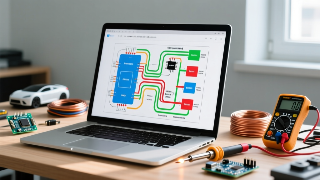

Decoding the Blueprint of Your EV Conversion
The DIY electric vehicle conversion landscape has evolved dramatically by 2026. With the availability of integrated kits like the NetGain HyPer 9 and Cascadia Motion systems, swapping an internal combustion engine for an electric drivetrain is more accessible than ever. However, the success of your build hinges entirely on your ability to interpret the manufacturer's electric vehicle wiring diagram PDF. Unlike standard 12V automotive wiring, EV schematics bridge high-voltage (HV) DC power and low-voltage (LV) logic circuits, where a single misread line can result in catastrophic component failure or severe safety hazards.
This step-by-step walkthrough will guide you through reading and executing the wiring sequence of a modern EV conversion schematic, focusing on a 144V to 400V DC architecture commonly found in passenger car and light truck conversions.
Expert Insight: Never rely solely on memory or forum screenshots. Always download the latest revision of the electric vehicle wiring diagram PDF directly from the component manufacturer's portal. Firmware updates in 2025 and 2026 have changed pinout assignments on popular motor controllers like the Curtis 1238E and Sevcon Gen4.
Phase 1: Pre-Wiring Safety and Tooling Requirements
Before tracing a single line on your schematic, you must prepare your workspace. High-voltage DC arcs do not self-extinguish like AC current, making proper tooling non-negotiable. According to the National Fire Protection Association (NFPA), working on EV systems requires specific insulated tooling and PPE to mitigate arc flash and shock risks.
- Multimeter: CAT III 1000V / CAT IV 600V rated (e.g., Fluke 87V or Fluke 1587 Insulation Multimeter).
- Hand Tools: VDE-certified 1000V insulated wrenches and screwdrivers (Klein Tools or Wiha).
- Crimping: Hydraulic hex-crimper with exact die sizes (e.g., 50mm² die for 1/0 AWG, 70mm² for 2/0 AWG). Avoid hammer crimpers, which compromise HV strand compression.
- PPE: Class 0 rubber insulating gloves (1000V DC rating) with leather protectors, and an arc-flash face shield for initial power-up.
Phase 2: Translating the Electric Vehicle Wiring Diagram PDF
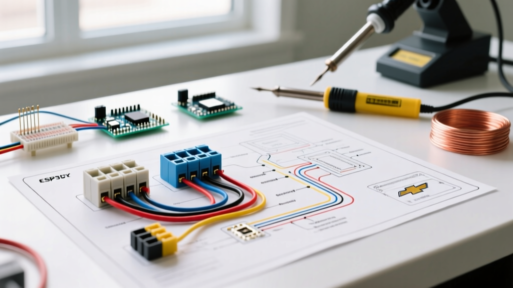
EV schematics use a distinct visual language to separate the HV traction circuit from the LV control circuit. When you open your electric vehicle wiring diagram PDF, look for the legend. Below is a translation matrix of standard symbols you will encounter in modern conversion manuals.
| Schematic Symbol | Component Name | Function in EV System | Typical Voltage / Current |
|---|---|---|---|
| Thick Solid Line (Red/Orange) | High-Voltage (HV) Cable | Carries main battery current to the inverter/motor. | 144V - 800V DC / 200A - 600A |
| Thin Solid Line (Blue/Yellow) | Low-Voltage (LV) Logic | 12V signals for contactor coils, BMS data, and interlocks. | 12V DC / < 5A |
| Rectangle with 'K' or Coil Symbol | Main Contactor | Heavy-duty relay that physically connects the battery pack to the controller. | Coil: 12V DC | Contacts: 400V+ |
| Zig-Zag Line in Parallel | Precharge Resistor | Limits inrush current to protect inverter capacitors during startup. | Rated for high Joule surge |
| Microchip with 'BMS' | Battery Management System | Monitors cell voltage/temp; opens the main contactor if limits are exceeded. | Logic: 12V | CANbus Data |
Phase 3: High-Voltage Wiring Walkthrough
The core of your electric vehicle wiring diagram PDF will detail the HV loop. This loop must be wired sequentially to ensure safety and proper precharge operation. We will use a standard 200kW inverter setup as our reference model.
Step 1: Battery Pack to Main Contactor and Emergency Disconnect
Begin at the positive terminal of your battery pack. The PDF will show a manual service disconnect or an Emergency Stop (E-Stop) switch wired in series.
Action: Route 2/0 AWG fine-strand copper welding cable (orange sheath per SAE J1766 standards) from the pack positive to the input stud of your HV contactor (e.g., Gigavac GX14 or TE Connectivity ECK100).
Torque Spec: M8 terminal nuts must be torqued to exactly 15 Nm. Apply a thin layer of NO-OX-ID A-Special conductive grease to the busbar interface to prevent galvanic corrosion, which causes high-resistance hot spots.
Step 2: The Precharge Circuit (Do Not Skip)
Every professional electric vehicle wiring diagram PDF includes a precharge circuit. Inverters contain massive DC bus capacitors. If the main contactor closes without precharging, the inrush current will act as a dead short, instantly welding the contactor contacts shut and potentially detonating the capacitors.
- Wire a secondary, smaller contactor (the precharge contactor) in parallel with the main contactor.
- Place a high-surge wirewound resistor (e.g., Vishay FVT series, 1000 Ohm, 50W) in series with this precharge contactor.
- When the key turns to 'ON', the BMS closes the precharge contactor first. Current flows through the resistor, slowly charging the inverter capacitors.
- Once the voltage on the inverter side reaches 90% of the pack voltage, the BMS closes the main contactor and opens the precharge contactor.
Step 3: Inverter to Traction Motor (3-Phase AC)
The output side of the inverter connects to the traction motor (e.g., NetGain HyPer 9 or Siemens 1PH8). The PDF will label these phases as U, V, and W.
Action: Use shielded 3-phase motor cable. The shielding must be grounded to the inverter chassis and the motor casing to prevent Electromagnetic Interference (EMI) from corrupting your LV CANbus signals. Strip the shield back exactly 15mm from the terminal lugs to prevent accidental shorting against adjacent phases.
Phase 4: Low-Voltage Logic and BMS Integration
The LV section of the schematic is where the 'brain' of the vehicle is wired. This requires meticulous attention to pinouts.
DC-DC Converter Wiring
Your EV still needs a 12V system for lights, wipers, and the BMS itself. The PDF will show a DC-DC converter (e.g., Vicor or TDK-Lambda) stepping down the HV pack to 13.8V - 14.4V. Wire the HV input directly to the *output* side of the main contactor. This ensures the DC-DC converter only powers up when the vehicle is 'ON', preventing parasitic drain on your main battery pack while parked.
BMS Sense Leads and Thermistors
If your PDF specifies a distributed BMS (like the Orion BMS 2 or ThunderSky), you will wire cell voltage sense taps.
Critical Warning: Never plug the BMS communication harness into the main unit until *every single cell tap wire* is verified with a multimeter. Plugging in a harness with reversed or skipped pins will instantly fry the BMS microcontroller, resulting in a $1,200+ replacement cost.
Troubleshooting Matrix: When the Wiring Fails
Even with a perfect electric vehicle wiring diagram PDF, physical execution errors occur. Use this matrix to diagnose common startup failures.
| Symptom on Power-Up | Probable Wiring Fault | Diagnostic Step |
|---|---|---|
| Main contactor clicks rapidly (chatters) | Precharge resistor failed open, or precharge contactor coil lacks 12V ground. | Measure voltage across inverter DC bus. If it stays near 0V during precharge, check resistor continuity. |
| Inverter throws 'Overcurrent' fault instantly | Motor phase wires (U, V, W) swapped or shorted to chassis ground. | Megger test the motor cables at 500V DC to check for insulation breakdown against the motor casing. |
| BMS opens contactor randomly under load | Voltage sense tap wires are loose, causing phantom voltage sag readings under high amperage. | Log BMS cell data via CANbus during a test drive. Look for single cells dropping >0.5V instantly under load. |
Final Verification and Legal Compliance
Before closing the hood, perform a 'dead short' test using your Fluke multimeter in continuity mode across the main HV positive and negative terminals (with contactors manually forced open). You should read infinite resistance (OL). If you read near zero ohms, you have a catastrophic short that will result in an arc flash upon battery connection.
Finally, ensure your conversion meets local road-legal requirements. The Alternative Fuels Data Center (AFDC) provides state-by-state guidelines on EV conversion inspections, emphasizing the necessity of proper HV cable routing, orange sheathing, and prominent high-voltage warning labels as dictated by NEC Article 625. By strictly following your electric vehicle wiring diagram PDF and adhering to these safety protocols, your EV conversion will be both reliable and road-ready.