
Understanding the LiftMaster Security+ 2.0 Terminal Block
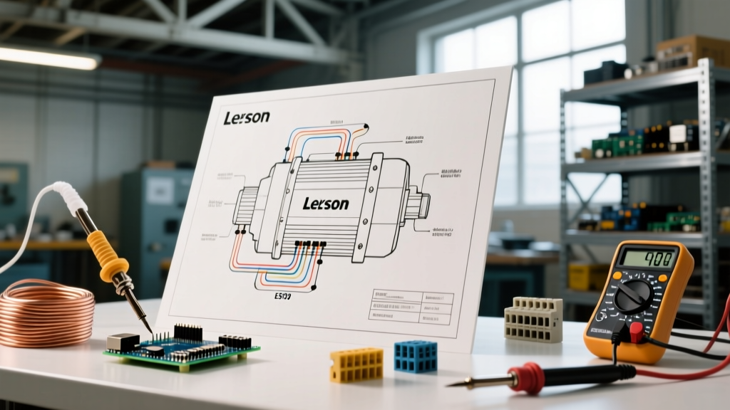
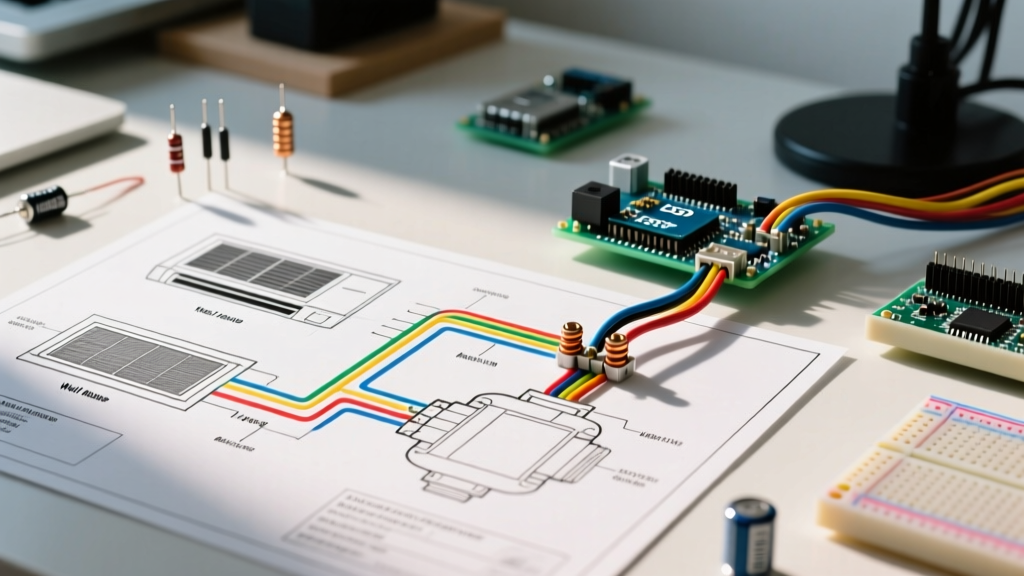
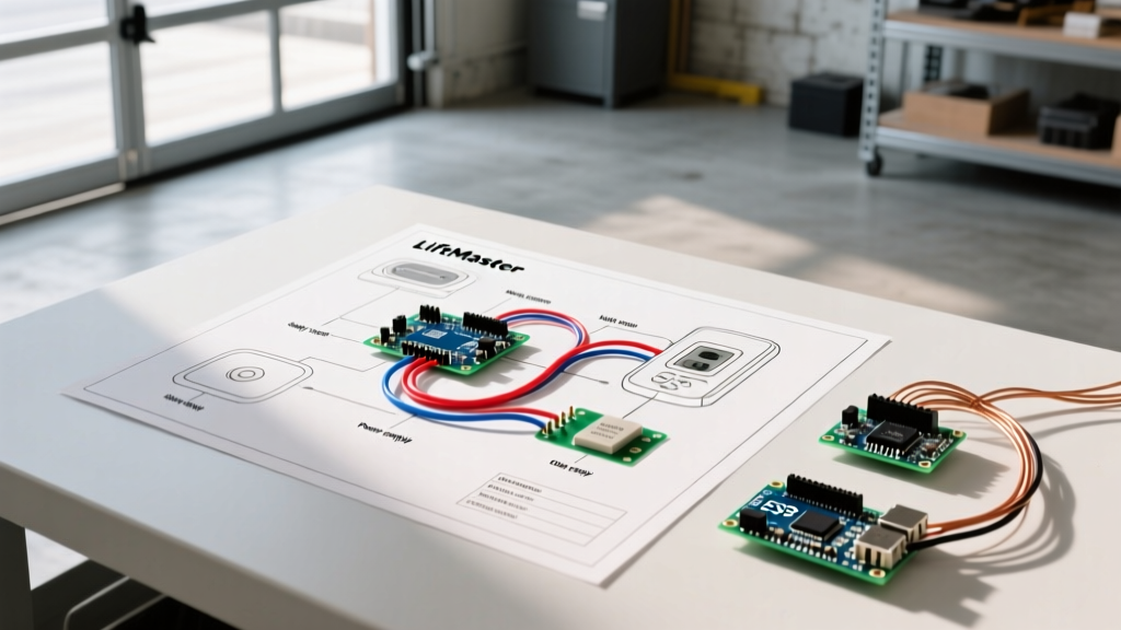
When interpreting the wiring diagram for LiftMaster garage door opener systems, the logic board terminal block is your central hub. Modern LiftMaster models—including the elite 8500W wall-mount, the 84505 Secure View belt drive, and the 8165W chain drive—utilize the proprietary Security+ 2.0 encrypted communication protocol. Unlike legacy dry-contact systems that simply completed a basic circuit, Security+ 2.0 sends multiplexed digital signals over low-voltage wiring.
The standard terminal block features three screw terminals, typically labeled 1, 2, and 3, or color-coded with Red and White markers:
- Terminal 1 (Red): Dedicated to the Red wire from the Multi-Function Wall Control Panel (e.g., model 882LMW or 883LMW).
- Terminal 2 (White/Common): Acts as the shared common ground. It accepts the White wire from the Wall Control Panel AND the White wire from the Sending (Amber LED) Safety Sensor.
- Terminal 3 (White/Sensor): Dedicated exclusively to the White wire from the Receiving (Green LED) Safety Sensor.
Expert Note: Never swap Terminal 2 and Terminal 3 for the sensors. While older LiftMaster models were forgiving with sensor polarity, the 2026 generation of Security+ 2.0 logic boards will throw a 4-flash error code if the sending and receiving sensor wires are reversed or crossed.
Wire Gauge and Material Specifications
Using the correct wire gauge is critical to prevent voltage drop, which is the leading cause of intermittent sensor failures in large or detached garages. Below is the definitive specification matrix for LiftMaster low-voltage and high-voltage connections.
| Application | Recommended Wire Type | Gauge (AWG) | Max Run Length | Notes & Edge Cases |
|---|---|---|---|---|
| Safety Sensors (Photo-Eyes) | Stranded Copper Bell Wire | 22 AWG | 100 ft | Use 20 AWG for runs exceeding 100 ft to mitigate voltage drop. |
| Wall Control Panel | Solid or Stranded Copper | 22 AWG | 150 ft | Do not use aluminum or copper-clad aluminum (CCA) wire. |
| 120V AC Power Supply | NM-B (Romex) or SJTOW Cord | 14 AWG (or 12 AWG) | 50 ft (Cord) | Must match the dedicated 15A or 20A branch circuit breaker rating. |
Step-by-Step: Wiring the Photoelectric Safety Sensors
The Consumer Product Safety Commission (CPSC) mandates that all residential garage door openers manufactured after 1993 must feature photoelectric reversal systems. LiftMaster's current 041-0136 safety sensor kit uses an infrared beam operating at 850nm.
1. Preparing the Sensor Wires
Strip exactly 7/16 inch of insulation from the ends of your 22 AWG bell wire. Twist the stranded copper tightly to prevent fraying. If you are extending the pre-attached sensor wires, use solder-seal heat shrink connectors rather than standard twist-on wire nuts, which can vibrate loose from the door's kinetic movement over time.
2. Routing and Securing
Route the sensor wires along the wall and ceiling joists. Never use metal staples to secure low-voltage bell wire; a staple driven too deeply will pierce the insulation, creating a micro-short that the logic board will read as an open circuit. Use insulated plastic cable clips spaced every 18 inches.
3. Terminal Connections
Connect the Sending Unit (Amber LED) wires to Terminals 2 (White) and 3 (White). Connect the Receiving Unit (Green LED) wires to Terminals 2 (White) and 3 (White). Because the sensors operate on a closed-loop circuit, polarity at the sensor end does not matter, but maintaining color consistency (White to White, White/Black to Red/Marked) drastically simplifies future troubleshooting.
Wiring the Multi-Function Wall Control Panel
Modern wall consoles like the 882LMW (Multi-Function) and 883LMW (with motion sensor) require specific attention to polarity. Unlike a simple push-button doorbell switch, these panels contain internal microprocessors that communicate with the opener's logic board.
- Run a continuous, unspliced 22 AWG wire from the wall control location to the motor head.
- Connect the Red wire from the wall panel to Terminal 1 (Red) on the opener.
- Connect the White wire from the wall panel to Terminal 2 (White) on the opener.
Warning: If you reverse the Red and White wires on an 882LMW panel, the LCD screen may illuminate, but the door will not respond to commands, and the logic board will fail to recognize the accessory. Always verify terminal polarity before tightening the set screws.
120V AC Power Requirements and NEC Compliance
While the low-voltage wiring diagram is complex, the 120V AC high-voltage supply is equally critical for safety and code compliance. According to the National Electrical Code (NEC) Article 210.8(A)(2), all 125-volt, single-phase, 15- and 20-ampere receptacles installed in garages must have GFCI protection.
However, LiftMaster openers with integrated battery backups (such as the 8500W) are notorious for nuisance-tripping older, overly sensitive GFCI receptacles during the battery charging cycle. To prevent your garage door from failing to open during a storm-induced power flicker, follow these 2026 best practices:
- Dedicated Circuit: Install a dedicated 15-amp or 20-amp circuit exclusively for the garage door opener.
- GFCI Breaker vs. Receptacle: Use a GFCI circuit breaker in the main panel rather than a GFCI wall receptacle. Breakers are less susceptible to the localized voltage spikes generated by the opener's DC motor capacitor bank.
- No Extension Cords: Using an extension cord violates UL 325 safety standards and instantly voids the LiftMaster warranty. If the provided power cord does not reach, hire a licensed electrician to install a new grounded receptacle within 3 feet of the motor head.
Troubleshooting Common Wiring Faults via LED Blink Codes
When the wiring diagram for LiftMaster garage door opener setups is misinterpreted or executed poorly, the motor unit's diagnostic LED will flash a specific sequence. Consult LiftMaster Official Support documentation for your exact model, but the universal Security+ 2.0 codes include:
- 1 Flash (Wire Open): One or more sensor wires are broken or disconnected at the terminal block. Check for severed wires near the floor where vehicles or tools may have snagged them.
- 2 Flashes (Wire Shorted): The Red and White wires for the wall control, or the sensor wires, are touching each other. This often happens if a metal staple pierced the wire jacket.
- 4 Flashes (Sensor Misalignment/Interference): The wiring is intact, but the infrared beam is blocked, the lenses are dirty, or direct afternoon sunlight is blinding the receiving sensor's photodiode. Install the included plastic sun shields to block ambient UV interference.
- 5 Flashes (RPM Sensor/Motor Issue): Not a wiring fault; indicates a logic board or motor tachometer failure requiring component replacement.
Frequently Asked Questions
Can I use Cat5e or Cat6 Ethernet cable for LiftMaster sensors?
Yes, but with caveats. Cat5e utilizes 24 AWG solid copper, which is slightly thinner than the recommended 22 AWG. For runs under 50 feet, Cat5e works perfectly and provides excellent shielding against EMI (Electromagnetic Interference) from nearby fluorescent lights or EV chargers. For runs over 50 feet, the voltage drop across 24 AWG wire may cause the green sensor LED to flicker. If using Cat5e, twist two pairs together (e.g., Solid Blue + Blue/White Stripe) to effectively increase the gauge to roughly 21 AWG.
Why does my wall control panel display 'Error 0' or fail to light up?
An unlit or 'Error 0' wall panel almost always indicates a short circuit in the low-voltage wiring. Disconnect the wall control wires from Terminals 1 and 2 at the motor head. If the panel on the motor unit stops flashing an error code, the fault lies in the wall wire. Inspect the wire path for pinches behind drywall or damage from drywall screws.
Is it safe to splice sensor wires in the attic?
While splicing is technically permissible using solder-seal heat shrink, every splice introduces a point of potential oxidation and resistance. In the high-humidity environment of an unconditioned attic, copper oxidation will eventually degrade the digital signal. Always attempt to run a single, continuous length of wire from the motor head down the wall to the sensor bracket.