
Why Direct-to-Battery Electric Fuel Pump Wiring Fails
In 2026, with E85 and flex-fuel conversions dominating the performance aftermarket, the electrical demands of modern fuel systems have never been higher. Upgrading to a high-flow pump is a common necessity, but many enthusiasts make a critical error: relying on the vehicle's original equipment manufacturer (OEM) wiring to supply power. OEM electric fuel pump wiring is typically designed for a 10-amp to 15-amp draw, utilizing thin 16 AWG or 18 AWG wires routed through long harness runs. When you connect a modern high-flow pump to this undersized circuit, the result is severe voltage drop, melted bulkhead connectors, and in extreme cases, electrical fires.
The Voltage Drop Danger: According to fluid dynamics and electrical engineering principles, an electric fuel pump loses approximately 10% of its volumetric flow for every 1-volt drop below its optimal 13.5V operating range. If your 18 AWG OEM wire drops the voltage to 10.5V under heavy load, your 'high-flow' pump is effectively performing like a stock unit, leading to lean conditions and catastrophic engine failure.
To deliver consistent fuel pressure and protect your engine control module (ECM), you must bypass the factory power circuit and implement a dedicated relay harness. This guide details the exact specifications, pinouts, and failure-prevention strategies required for safe, high-amperage electric fuel pump wiring.
Core Components for a Safe Fuel Pump Relay Harness
Building a robust harness requires automotive-grade materials capable of withstanding under-hood temperatures and high current loads. Standard PVC wire is unacceptable; you must use cross-linked polyethylene (TXL or GXL) wire, which meets SAE J1128 standards for high-temperature resistance up to 150°C.
| Component | Specification | Purpose & Expert Notes |
|---|---|---|
| Relay | Bosch-style 40A SPST (Standard ISO Mini) | Handles high amperage. Use sealed relays (e.g., Tyco V23234) if mounted in the trunk or near the fuel tank. |
| Power Wire | 10 AWG TXL / GXL | Carries main current from battery to relay, and relay to pump. 10 AWG prevents voltage drop on runs over 6 feet. |
| Ground Wire | 10 AWG TXL / GXL | Must ring-terminal directly to a clean, bare-metal chassis point. Never rely on seatbelt bolts or painted surfaces. |
| Trigger Wire | 14 AWG or 16 AWG | Carries low-amperage signal from the OEM fuel pump relay or ECU to switch the 40A relay. |
| Main Fuse | 30A or 40A ANL / ATC | Must be located within 12 inches of the battery positive terminal to protect the entire harness from short circuits. |
| Flyback Diode | 1N4001 or 1N4007 | Crucial if triggering directly from an ECU pin. Prevents back-EMF voltage spikes from frying the ECU driver. |
Step-by-Step Electric Fuel Pump Wiring Diagram & Pinout
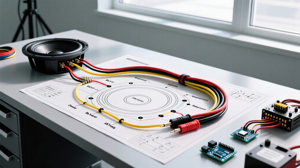
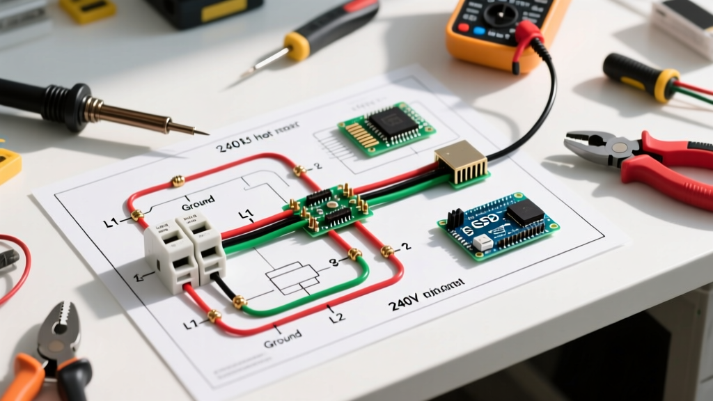
A standard Bosch-style 40A relay features five pins, though a 4-pin SPST (Single Pole Single Throw) is preferred for fuel pumps to eliminate internal resistor heat generation. Below is the exact pinout for wiring your relay harness safely.
- Pin 30 (Main Power In): Connect a 10 AWG red wire from the vehicle's battery positive terminal. Crucial: Install a 30A or 40A waterproof fuse holder on this wire within 6 to 12 inches of the battery post.
- Pin 87 (Switched Power Out): Connect a 10 AWG wire running directly to the positive terminal of the electric fuel pump. Use a weather-pack connector or heat-shrink ring terminal at the pump to prevent fuel vapor intrusion.
- Pin 86 (Trigger In): Connect a 14 AWG wire to your 12V trigger source. This should ideally be the output side of the vehicle's factory fuel pump relay. This ensures the new high-flow pump only runs when the ECU commands the OEM relay to engage (during crank and run states).
- Pin 85 (Ground): Connect a 14 AWG wire to a verified, unpainted chassis ground. Use a multimeter to verify continuity to the battery negative terminal (resistance should be less than 0.5 ohms).
Calculating Wire Gauge for High-Flow Pumps
Different pumps draw vastly different amperages, especially as fuel pressure rises. According to electrical load calculators referenced by electrical engineering resources, wire length and amperage dictate your AWG requirement. Below is a comparison of popular 2026 aftermarket pumps and their wiring needs.
| Pump Model | Flow Rate (LPH) | Peak Amp Draw (at 60 PSI) | Recommended Wire Gauge (Up to 10ft Run) |
|---|---|---|---|
| OEM Replacement (e.g., Delphi) | 190 - 255 | 12A - 15A | 12 AWG |
| AEM 50-1085 (340 LPH) | 340 | 18A - 22A | 10 AWG |
| Walbro F90000274 (450 LPH) | 450 | 25A - 30A | 10 AWG (8 AWG for runs >12ft) |
| Deatschwerks DW400 | 415 | 20A - 26A | 10 AWG |
The Hidden ECU Killer: Back-EMF and Flyback Diodes
One of the most expensive mistakes in custom electric fuel pump wiring occurs when a tuner decides to trigger the aftermarket relay directly from an ECU's auxiliary output pin, bypassing the OEM relay entirely. When a relay coil is de-energized, the collapsing magnetic field generates a high-voltage reverse spike (Back-Electromotive Force, or Back-EMF). This spike can easily exceed 50 volts, instantly frying the delicate solid-state transistor inside your ECU.
The Solution: Solder a standard 1N4001 rectifier diode across the relay's trigger pins (85 and 86). The silver stripe on the diode must face Pin 86 (the positive trigger side). This creates a 'flyback' circuit, allowing the voltage spike to recirculate harmlessly through the coil and dissipate as a negligible amount of heat. As noted in automotive wiring tech guides, spending $0.10 on a diode can save you a $1,500 ECU replacement.
Common Failure Modes & Troubleshooting
Even with a perfect diagram, environmental factors and poor execution can lead to fuel starvation. Watch for these specific failure modes:
- The 'Priming' Pulse Issue: Modern ECUs pulse the fuel pump for 2-3 seconds when the ignition is turned to the 'ON' position to prime the rails. If your trigger wire is tapped into an ignition-switched 12V source (like a radio harness) instead of the OEM fuel pump circuit, the pump will run continuously whenever the key is on, flooding the charcoal canister and draining the battery.
- Ground Loop Voltage Drop: If the pump ground is tied to a taillight ground or a shared chassis point, the pump will modulate its speed based on the electrical load of the brake lights or rear defroster. Always run a dedicated 10 AWG ground wire directly to the chassis or battery negative.
- Melted Bulkhead Connectors: The factory connector at the top of the fuel tank (the hat assembly) is often rated for only 15 amps. Passing 30 amps through it will melt the plastic pins. You must bypass the factory hat connector by drilling a new hole, installing a sealed bulkhead fitting, and running your 10 AWG wire directly to the pump inside the tank.
Expert Tips for Routing and Environmental Protection
When routing your new 10 AWG harness from the engine bay to the rear-mounted fuel tank, never run the wires parallel to high-energy ignition coil wires or O2 sensor harnesses, as this can induce electromagnetic interference (EMI). Always cross high-voltage and low-voltage wiring at 90-degree angles.
Use split-loom tubing and high-temperature Tesa tape to protect the harness from exhaust radiant heat. Where the harness passes through the firewall or trunk pan, you must use a reinforced rubber grommet. Sharp sheet metal will eventually vibrate through the wire insulation, causing a dead short and a potential fuel fire. Secure the wiring every 12 inches using UV-resistant zip ties or aluminum P-clamps with rubber inserts.
Frequently Asked Questions (FAQ)
Can I use a PWM (Pulse Width Modulation) fuel pump controller instead of a standard relay?
Yes, and for high-horsepower builds in 2026, it is highly recommended. A PWM controller (like the Aeromotive FSC or Holley VR2) uses high-frequency switching to vary pump speed based on fuel pressure demand. This reduces fuel temperature (preventing vapor lock) and extends pump life. However, PWM controllers still require heavy-gauge (8 AWG or 10 AWG) wiring from the battery, as they handle the full amperage load of the pump.
My new fuel pump whines loudly after wiring. Is it defective?
Not necessarily. High-flow gerotor and turbine pumps naturally operate at higher decibel levels than stock units. However, excessive whining often indicates cavitation caused by a clogged pre-pump filter (sock) or an undersized suction line. Ensure your pickup sock is rated for E85 and is not restricted by the baffling inside the fuel tank.
Do I need an inertia switch for safety?
If your vehicle did not come with one from the factory (common in older muscle cars or tube-chassis race cars), installing an inertia cutoff switch on the trigger wire (Pin 86) is a critical safety upgrade. In the event of a collision, the switch will instantly cut power to the relay, preventing high-pressure fuel from spraying in an accident.