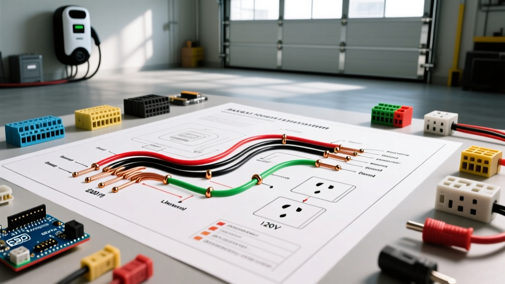

Understanding the 240V Electric Hot Water Wiring Diagram
Wiring a standard electric storage tank water heater is a foundational electrical task, but it involves high-amperage 240V circuits that leave zero margin for error. Whether you are installing a new 50-gallon Rheem PROE50 T2 RH95 or replacing the internal thermostats on an existing Bradford White unit, understanding the exact electric hot water wiring diagram is critical for safety and code compliance.
Most residential electric water heaters utilize two 4500-watt heating elements operating on a 240-volt circuit. This configuration draws approximately 18.75 amps per element. Because the elements operate in a non-simultaneous sequence (the upper element heats first, then hands off power to the lower element), the circuit only needs to be sized for a single 4500W load. According to the National Electrical Code (NEC), this requires a dedicated 30-amp double-pole breaker and 10 AWG copper wire.
Crucial Distinction for 2026 Installations: This guide applies strictly to standard electric resistance water heaters. If you are installing a modern Hybrid Heat Pump Water Heater (like the Rheem ProTerra or AO Smith Signature), refer to the manufacturer's specific schematic, as many newer heat pump models require a 15-amp or 20-amp 120V/240V dedicated circuit to support the compressor and control boards.
Pre-Wiring Checklist and Material Requirements
Before pulling any wire or terminating connections, ensure you have the correct materials. Using undersized wire or incorrect breakers is a leading cause of melted junction boxes and electrical fires. As of 2026, expect to spend roughly $120 to $180 on materials for a standard 40-foot run, excluding the water heater unit itself.
| Component | Specification | Example Model / Brand | Estimated Cost (2026) |
|---|---|---|---|
| Circuit Breaker | 30A, 2-Pole, 240V | Square D QO230 / Eaton BR230 | $18 - $25 |
| Wire (Cable) | 10/2 NM-B with Ground (Copper) | Cerrowire / Southwire | $1.10 - $1.40 / ft |
| Disconnect Switch | 30A, 240V, Non-Fused (if required) | Siemens Q230 / Eaton DPU2222R | $20 - $35 |
| Wire Connectors | Purple or Yellow (rated for 10 AWG) | Ideal Wire-Nut 341 | $5 / pack |
| Clamps | 3/8" NM Cable Connectors | Halex 27511 | $2 / pair |
Step-by-Step Wiring Walkthrough
Follow this sequential workflow to ensure your electric hot water wiring diagram is executed safely and passes local Authority Having Jurisdiction (AHJ) inspections.
Step 1: Panel Preparation and Breaker Installation
Turn off the main breaker to de-energize the panel. Install your 30-amp double-pole breaker into an available two-slot space. Connect the 10 AWG black wire to one brass terminal and the re-identified white wire (see Step 2) to the other brass terminal. Connect the bare copper ground wire to the panel's ground bus bar.
Pro-Tip (Torque Specifications): Modern NEC guidelines (110.14(D)) mandate that electrical connections be torqued to the manufacturer's specifications. For most 30A Square D and Eaton breakers, the terminal screw torque requirement is between 20 and 25 inch-pounds. Use a calibrated torque screwdriver to prevent loose connections that cause arcing over time.
Step 2: Routing the Cable and Re-identifying the Neutral
Route the 10/2 NM-B cable from the panel to the water heater location. Secure the cable with staples within 12 inches of the panel and every 4.5 feet along the run, per NEC Article 334.30.
NEC 200.7(C) Violation Warning: Standard 10/2 Romex contains a black (hot), white (neutral), and bare (ground) wire. Because a standard 240V water heater does not use a neutral, the white wire is being used as a second hot leg. You must wrap both ends of the white wire with black or red electrical tape, or paint it, to re-identify it as an ungrounded (hot) conductor. Failing to do so is an immediate code violation.
Step 3: The Disconnecting Means
According to NEC Article 422.31(B), appliances rated over 300 watts and 120 volts must have a disconnecting means within sight. If your electrical panel is not within 50 feet and in direct line-of-sight of the water heater, you must install a 30A 240V non-fused disconnect switch on the wall adjacent to the unit. Wire the incoming 10/2 into the 'LINE' side of the disconnect, and run a short whip of 10/2 from the 'LOAD' side to the water heater's junction box.
Step 4: Terminating at the Water Heater Junction Box
Open the junction box cover on the top or side of the water heater. Install a 3/8-inch NM cable clamp to secure the wire and prevent the sharp metal edges from slicing the cable sheathing. Strip the outer sheathing so that exactly 1/4 inch extends inside the box.
- Grounding First: Connect the bare copper ground wire from your cable to the green ground screw inside the junction box, and pigtail it to the water heater's internal ground wire using a purple wire nut.
- Hot Leg 1 (L1): Connect the black wire from your cable to the black wire leading to the upper thermostat using a wire nut.
- Hot Leg 2 (L2): Connect the re-identified white wire from your cable to the white (or red) wire leading to the upper thermostat.
Gently fold the wires into the box, ensuring no bare copper is exposed outside the wire nuts, and secure the metal cover plate.
Internal Thermostat Wiring: The Non-Simultaneous Logic
To truly understand the electric hot water wiring diagram, you must understand how the internal thermostats manage power. Residential dual-element heaters use a non-simultaneous operation to prevent overloading the 30-amp circuit.
- Cold Start: When the tank is full of cold water, the upper thermostat receives 240V from the junction box. It routes power to the upper 4500W element.
- Handoff: Once the top third of the tank reaches the set temperature (usually 120°F), the upper thermostat's internal switch flips. It cuts power to the upper element and sends 240V down to the lower thermostat.
- Maintenance: The lower thermostat then powers the lower element to heat the remaining water. As hot water is drawn from the top of the tank, cold water enters the bottom, triggering the lower element to cycle on and off to maintain the baseline temperature.
If your water heater is running out of hot water quickly, the issue is rarely the main wiring diagram. It is almost always a failed upper thermostat, a burnt-out lower element, or a tripped high-limit reset button (ECO) on the upper thermostat.
Common Failure Modes and Troubleshooting
Even with a perfect installation, environmental factors and component degradation can cause issues. Here is how to diagnose the most common failures:
1. Tripped Breaker and Melted Wire Nuts
The Cause: Loose connections at the junction box. If the wire nuts were not twisted tightly enough, the high resistance creates intense heat, melting the plastic and eventually tripping the 30A breaker via thermal overload.
The Fix: Cut back the burnt wire to clean, shiny copper. Use new, high-temperature purple wire nuts rated specifically for 10 AWG solid wire. Ensure no bare wire is visible below the skirt of the nut.
2. 'Dry Firing' a New Element
The Cause: If you replace a heating element and turn the 30A breaker on before the tank is 100% full of water, the element will superheat and burn out in seconds. This is known as dry-firing.
The Fix: Always open a hot water faucet in the house and wait for a steady, sputter-free stream of water before energizing the circuit. If an element dry-fires, it cannot be repaired; it must be replaced. Refer to the Department of Energy's water heating guidelines for proper element sizing and efficiency maintenance.
3. 208V vs. 240V Element Mismatch
The Cause: If you live in a multi-family building or an area with a 120/208V three-phase wye power supply, feeding a standard 240V 4500W element with only 208V will reduce its output to roughly 3375 watts. Your recovery time will be painfully slow.
The Fix: Verify your actual line-to-line voltage with a multimeter. If you have 208V, you must purchase heating elements specifically rated for 208V / 3500W to maintain proper amperage draw and recovery times.
Final Safety and Code Compliance Checks
Before restoring power to the panel, perform a final visual inspection. Ensure the ground wire is securely terminated, the cable sheathing is clamped, and the disconnect switch (if installed) is in the 'OFF' position. Turn on the main breaker, flip the 30A double-pole breaker to 'ON', and finally, engage the local disconnect switch.
Use a non-contact voltage tester or a multimeter at the upper element terminals to verify that 240V is present. As always, electrical work carries inherent risks. If you are unsure about your local amendments to the NEC, or if your panel lacks the physical space for a new double-pole breaker, consult a licensed master electrician. For comprehensive workplace and residential electrical safety standards, review the OSHA electrical safety guidelines to ensure your work environment remains secure.