
Understanding the 5-Pin Relay: SPDT Architecture
When working with automotive, marine, or industrial 12V/24V DC systems, the 5-pin relay is the most versatile electromechanical switch at your disposal. Unlike the simpler 4-pin SPST (Single Pole Single Throw) relay, a 5-pin relay operates as an SPDT (Single Pole Double Throw) device. This means it can route power to two different circuits depending on whether the coil is energized or at rest.
Whether you are wiring off-road LED light bars, dual-battery isolators, or winch solenoids, understanding the exact wiring diagram for a 5 pin relay is critical to preventing short circuits and component damage.
The Standard DIN 72552 Pinout
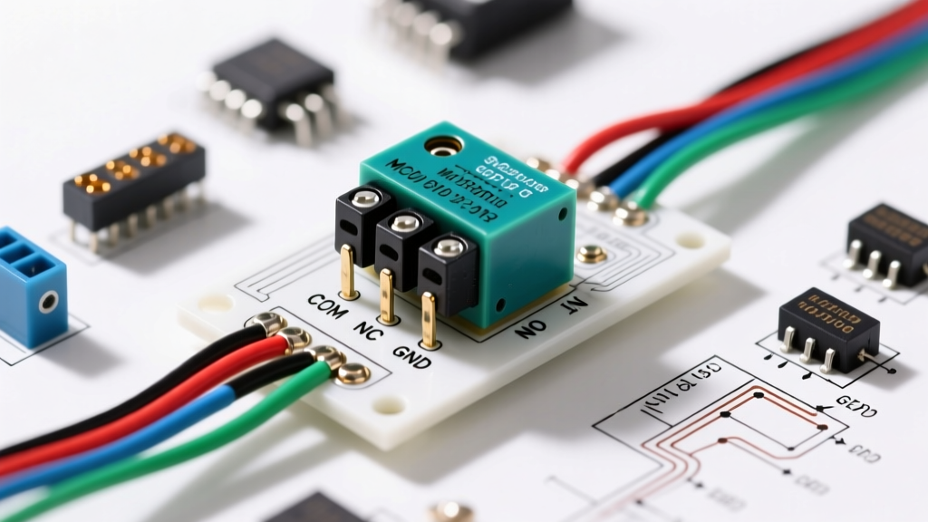
Most automotive relays follow the German DIN 72552 standard for terminal numbering. Here is the exact function of each pin on a standard ISO mini relay:
| Terminal | Function | Circuit Type | Description |
|---|---|---|---|
| 85 | Coil Ground | Control | Connects to chassis ground or ECU switched ground. |
| 86 | Coil Power | Control | Connects to 12V+ trigger (e.g., ignition switch, toggle switch). |
| 30 | Common Input | Load | Main power feed from the battery (always fused). |
| 87 | Normally Open (NO) | Load | Outputs power ONLY when the relay coil is energized. |
| 87a | Normally Closed (NC) | Load | Outputs power when the relay is AT REST (de-energized). |
Wiring Diagram for a 5 Pin Relay: Step-by-Step Execution
To properly wire this component, you must separate the system into two isolated circuits: the control circuit (low current) and the load circuit (high current).
Step 1: Wiring the Control Circuit (Pins 85 & 86)
The electromagnetic coil inside a standard 12V relay typically has a resistance of 60 to 90 ohms, drawing roughly 150mA of current. Because this current is minimal, you can use 18 AWG wire for the control side.
- Run a wire from your trigger source (e.g., a dashboard toggle switch receiving ignition-switched 12V) to Pin 86.
- Run a wire from Pin 85 to a clean, bare-metal chassis ground.
Pro-Tip (Flyback Diode): If your trigger signal comes from a sensitive solid-state ECU driver or a programmable logic controller (PLC), solder a 1N4007 flyback diode across pins 85 and 86 (stripe facing Pin 86). When the coil de-energizes, it generates a high-voltage inductive spike that can fry solid-state switches. The diode safely recirculates this spike.
Step 2: Wiring the Load Circuit (Pins 30, 87, and 87a)
The load circuit handles the heavy lifting. For a standard 30A/40A relay, the contacts can handle significant current, but inrush spikes must be considered.
- Pin 30 (Common): Connect this directly to the positive battery terminal. Crucial: Install an inline fuse (e.g., 30A MAXI fuse) within 6 inches of the battery connection to protect the main feed wire.
- Pin 87 (Normally Open): Wire this to the positive terminal of your primary accessory (e.g., a 120W LED light bar). This accessory will only turn ON when the switch is flipped.
- Pin 87a (Normally Closed): Wire this to a secondary accessory (e.g., auxiliary daytime running lights) that you want to turn OFF when the primary accessory turns ON. If you do not need a secondary circuit, simply cap this wire with heat shrink or electrical tape.
Component Selection: Real-World Models and Specifications
Not all relays are created equal. Cheap, unbranded relays often use inferior copper alloys for the contacts, leading to high resistance and premature failure. For mission-critical applications, specify relays from established manufacturers.
| Manufacturer | Model / Series | Contact Rating | Coil Voltage | Avg. Price (2026) |
|---|---|---|---|---|
| Bosch | 0332014150 | 30A (NO) / 20A (NC) | 12V DC | $5.50 - $7.00 |
| Omron | G8P-1A4P | 30A (NO) | 12V DC | $3.50 - $5.00 |
| Littelfuse | RC Series | 40A (NO) / 30A (NC) | 12V DC | $6.00 - $8.50 |
| Tyco / TE | V23134 (Black) | 40A (NO) / 35A (NC) | 12V DC | $8.00 - $12.00 |
For deeper technical specifications on automotive relay tolerances and lifecycle testing, refer to the Littelfuse Relay Catalog or comprehensive wiring guides like those found on The12Volt.
Wire Gauge Selection and Fusing Matrix
Using the correct wire gauge prevents voltage drop and fire hazards. The following matrix assumes a standard 12V DC system with a maximum 3% voltage drop over a 15-foot total circuit length (power + ground).
| Max Continuous Load | Recommended Wire Gauge | Inline Fuse Size | Typical Application |
|---|---|---|---|
| 10A | 16 AWG | 15A | Horn, small fuel pumps |
| 20A | 14 AWG | 20A or 25A | Cooling fans, winch solenoids |
| 30A | 12 AWG | 30A or 35A | Large LED light bars, compressors |
| 40A | 10 AWG | 40A or 50A | High-amperage inverters, starters |
Troubleshooting Common Failure Modes
When a circuit fails, the relay is often blamed, but the root cause may lie elsewhere. Use a digital multimeter (DMM) to diagnose these specific failure modes:
1. Contact Welding (Stuck Closed)
Symptom: The accessory stays on even when the relay is removed or the control circuit is off.
Cause: Switching highly inductive loads (like motors) or incandescent bulbs with massive inrush currents causes arcing across the contacts. The heat melts the contact pads together.
Fix: Upgrade to a relay with a higher amperage rating or one specifically rated for tungsten loads. Add a snubber circuit for inductive loads.
2. Coil Burnout (Open Circuit)
Symptom: The relay never clicks; no continuity across pins 85 and 86.
Cause: Overvoltage (e.g., an alternator voltage regulator failing and pushing 16V+ into a 12V system) or prolonged duty cycling beyond the relay's thermal limits.
Fix: Test system voltage with the engine running. Replace the relay and install a transient voltage suppressor (TVS) diode if overvoltage spikes are common.
3. High Contact Resistance (Voltage Drop)
Symptom: The accessory operates weakly (e.g., lights are dim, motor spins slowly).
Cause: Carbon buildup or oxidation on the internal contacts due to moisture ingress or age.
Test: Set your DMM to DC Volts. Place the red probe on Pin 30 and the black probe on Pin 87 while the relay is energized and under load. A healthy relay will show a voltage drop of less than 0.1V. If you read 1.5V or higher, the internal contacts are degraded and the relay must be replaced.
Frequently Asked Questions
Can I use a 5-pin relay in place of a 4-pin relay?
Yes. A 5-pin relay is fully backward-compatible with 4-pin applications. Simply wire pins 85, 86, 30, and 87 exactly as you would on a 4-pin relay, and leave pin 87a (Normally Closed) disconnected and insulated. The internal mechanics will function identically to an SPST relay.
Does polarity matter on pins 85 and 86?
For standard electromechanical relays, polarity does not matter; the coil will energize regardless of which pin receives 12V+ and which receives ground. However, if you are using a relay with an internal suppression diode or resistor (often marked with a diode symbol on the casing), polarity does matter. Pin 86 must be positive and Pin 85 must be ground, otherwise the internal diode will short the circuit and blow your control fuse.
Why is my relay getting hot to the touch?
A relay coil will naturally generate some heat (roughly 1.5 to 2 watts of dissipation for a standard 12V coil). However, if the plastic casing is too hot to touch, you likely have high resistance on the load contacts (causing I²R heating) or you are exceeding the continuous current rating of the relay. Ensure your load does not exceed 80% of the relay's nominal rating for continuous duty applications.