
The Role of the Junction Box in Panel-to-Subpanel Routing
When expanding an electrical system, the main service panel rarely has a direct, unobstructed path to a new subpanel or heavy load. This is where the junction box becomes critical. Understanding the correct wiring diagram for junction box configurations ensures that feeder cables from your main breaker panel are safely spliced, routed, and protected. From a Panel & Breaker Guide perspective, the junction box is not merely a plastic or metal enclosure; it is a calculated transition point governed by strict National Electrical Code (NEC) volume and bending radius requirements.
In 2026, with the widespread adoption of high-draw EV chargers and whole-home heat pumps, electricians and advanced DIYers are frequently pushing 100A to 125A feeder circuits through intermediate enclosures. A flawed splice or an undersized box can lead to catastrophic thermal failures at the breaker terminals or inside the enclosure itself.
Standard Feeder Routing Topology
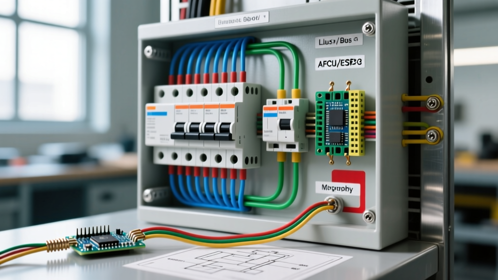
Before pulling wire, you must visualize the topology. A standard 100A, 240V subpanel feed requires four conductors: two ungrounded (hot) legs, one grounded (neutral) conductor, and one equipment grounding conductor (EGC). When these conductors pass through an intermediate junction box, the wiring diagram dictates the following flow:
- Source Side: 2 AWG THHN/THWN-2 copper conductors originate from a 100A 2-pole breaker (e.g., Square D HOM2100) in the main panel.
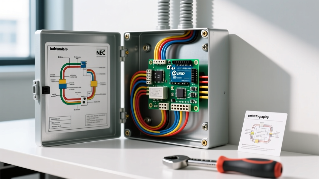
- Transition Point: Conductors enter the junction box via 1.5-inch PVC or EMT conduit. Inside the box, they are spliced using insulated tap blocks to extend the run, or simply looped if the box acts strictly as a pull point.
- Load Side: The conductors exit the box and terminate at the main lugs of the subpanel.
Expert Insight: Never splice the Equipment Grounding Conductor (EGC) using standard wire nuts on feeder circuits. For 2 AWG wire, you must use listed mechanical connectors, such as Polaris insulated tap blocks, or exothermic welding to ensure a low-impedance fault path back to the main panel's ground bus.
NEC Box Fill Calculations: Sizing the Enclosure
The most common failure in junction box planning is ignoring NEC Article 314.16. If you are splicing conductors inside the box, every conductor requires a specific volume allowance. If the box is too small, heat cannot dissipate, and the insulation on the THHN wire will degrade prematurely, eventually causing a short circuit that the upstream breaker may not trip fast enough to prevent.
Volume Allowance per Conductor (NEC Table 314.16(B))
| Wire Size (AWG/kcmil) | Volume per Conductor (Cubic Inches) | Total Volume for 4 Spliced Feeders |
|---|---|---|
| #4 AWG | 2.0 cu in. | 16.0 cu in. (8 conductors total in/out) |
| #2 AWG | 3.0 cu in. | 24.0 cu in. (8 conductors total in/out) |
| #1/0 AWG | 4.0 cu in. | 32.0 cu in. (8 conductors total in/out) |
| #2/0 AWG | 4.5 cu in. | 36.0 cu in. (8 conductors total in/out) |
Note: If using 2 AWG copper for a 100A feed, you have 4 incoming wires and 4 outgoing wires, totaling 8 current-carrying and grounding conductors. 8 x 3.0 = 24 cubic inches minimum. However, you must also account for the physical volume of the Polaris tap blocks (typically adding 2 to 4 cubic inches per block). A standard 8x8x4 inch NEMA 3R enclosure (like the Hoffman H884RTB, retailing around $165) provides 256 cubic inches, offering ample room for heat dissipation and wire bending.
Step-by-Step Execution: Splicing 100A Feeders
When executing the physical wiring diagram for junction box splices, precision and torque are non-negotiable. Loose connections on high-amperage feeder circuits are the leading cause of residential electrical fires.
Phase 1: Preparation and Stripping
- De-energize and Lockout: Turn off the main breaker. Verify zero voltage at the panel bus bars using a CAT IV multimeter.
- Strip the Insulation: Use a calibrated wire stripper to remove exactly 1.5 inches of insulation from the 2 AWG THHN wires. Do not nick the copper strands; damaged strands increase localized resistance and heat.
- Mount the Tap Blocks: Secure Polaris ITPB-3 (3-port insulated tap blocks) to the backplane of the junction box using #10 stainless steel self-tapping screws. Space them at least 2 inches apart to prevent phase-to-phase tracking.
Phase 2: Termination and Torque
- Insert Conductors: Push the stripped ends of the incoming and outgoing hot, neutral, and ground wires into the respective tap blocks. Ensure no bare copper is exposed outside the insulated housing.
- Apply Torque: This is the most critical step. According to manufacturer specifications and NEC 110.14(D), you must use a calibrated torque screwdriver. For #2 AWG wire in a Polaris block, the required torque is typically 35 inch-pounds. Overtightening will shear the aluminum set-screws; undertightening will cause arcing under load.
- Secure the Lids: Seal the tap blocks and close the junction box enclosure. Ensure the NEMA rating matches your environment (e.g., NEMA 3R for outdoor or damp garage locations).
Pull Box vs. Junction Box: The Bending Radius Factor
If your wiring diagram utilizes the enclosure strictly as a pull box (meaning the wires pass straight through without being spliced), NEC Article 314.28 applies. For a straight pull, the length of the box must be at least eight times the trade diameter of the largest conduit entering the box. If you are using 1.5-inch PVC conduit, the pull box must be at least 12 inches long (1.5 x 8 = 12). Ignoring this rule results in damaged wire insulation as electricians forcefully yank 2 AWG wires through tight 90-degree sweeps, exposing the system to ground faults.
Critical Edge Cases and Failure Modes
Even with a perfect wiring diagram, real-world installations encounter edge cases that can compromise the panel and breaker system.
- The Floating Neutral Disaster: If the junction box is metallic, the EGC must be bonded to the box via a grounding bushing or internal ground screw. However, the neutral conductor must remain completely isolated from the box and the ground. Bonding the neutral in a downstream junction box creates parallel neutral paths, causing the metal enclosure to carry return current, which can result in lethal shock hazards.
- Harmonic Heating in Shared Neutrals: If your junction box is routing multi-wire branch circuits (MWBC) or 3-phase feeders to a commercial subpanel, non-linear loads (like LED drivers and VFDs) generate triplen harmonics. These harmonics add up on the neutral bus. If your wiring diagram did not account for a 200% oversized neutral conductor, the neutral tap block inside the junction box will overheat, even if the phase breakers never trip.
- Aluminum-to-Copper Galvanic Corrosion: If your main panel uses 1/0 AWG aluminum feeder wire (XHHW-2) and you are transitioning to 2 AWG copper inside the junction box, you must use tap blocks specifically rated for CU9AL (Copper-to-Aluminum) connections and apply Noalox antioxidant paste. Failing to do so will result in galvanic corrosion, increasing resistance and eventually melting the tap block within 3 to 5 years.
Frequently Asked Questions (FAQ)
Can I use a standard PVC round box for a 100A subpanel feed?
No. Standard 4-inch round PVC boxes lack the cubic inch volume and the physical dimensions required for the bending radius of 2 AWG or 1/0 AWG feeder wires. You must use a deep, square or rectangular metallic or heavy-duty fiberglass enclosure rated for the specific volume and environmental conditions.
Does the junction box need its own dedicated breaker?
No. A junction box is a passive enclosure; it does not require a dedicated breaker. It is protected by the upstream breaker in the main panel that feeds the circuit passing through it. The breaker size must be matched to the lowest ampacity of the wire entering or exiting the box.
Final Thoughts on Panel Integration
Executing a flawless wiring diagram for junction box connections is about respecting the physics of electricity and the letter of the NEC. By correctly calculating box fill, utilizing insulated mechanical tap blocks, and applying precise torque to your terminations, you ensure that your panel and breaker system operates safely for decades. For further reading on enclosure sizing and code compliance, always consult the latest National Electrical Code guidelines published by the NFPA and reference technical bulletins from Electrical Contractor Magazine for real-world code enforcement scenarios.