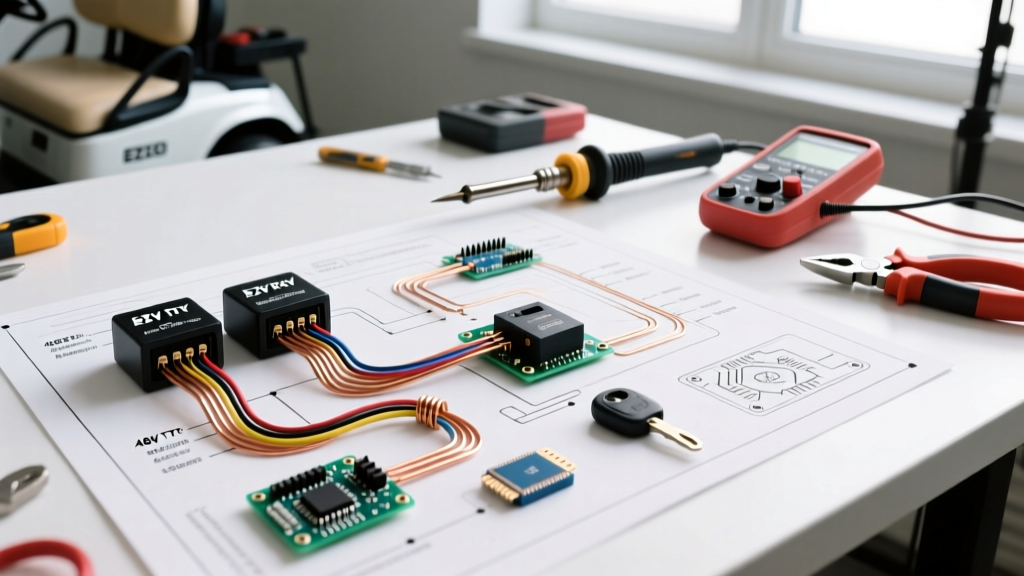

Decoding the EZGO Wiring Diagram: TXT vs. RXV Architectures
When an electric golf cart refuses to move, stutters under load, or fails to charge, the difference between a costly dealer visit and a $20 DIY fix lies in your ability to read an EZGO wiring diagram electric golf cart schematic. EZGO dominates the personal and fleet market, but their electrical architectures have evolved drastically. To troubleshoot effectively in 2026, you must first identify whether you are working on a legacy TXT platform or a modern RXV platform, as their wiring topologies are fundamentally incompatible.
The 48V TXT Series/DC Schematic
The classic EZGO TXT (particularly the 48V series models produced up through the early 2010s) relies on a relatively simple, high-current DC architecture. The wiring diagram for a 48V TXT centers around a heavy-duty main solenoid (often an Albright SW200 or equivalent), a separate Forward/Reverse (F&R) mechanical switch, and a DC motor controller (typically a Curtis 1268). The diagram will show a distinct separation between the high-current traction circuit (thick red and black cables) and the low-current logic circuit (16-18 AWG wires routing through microswitches).
The 48V RXV AC/DC Schematic
The RXV platform eliminated the traditional F&R switch, the tow/run switch, and the external solenoid. Instead, the RXV wiring diagram reveals a highly integrated AC motor controller (often Danaher or GE) that handles directional logic internally via software. The RXV relies on a Motor Controller Optical Regulator (MCOR) for throttle input and an onboard Delta-Q charger. Troubleshooting an RXV requires tracing 5V reference signals and CAN-bus communication lines rather than simply checking for 48V continuity.
Essential Diagnostic Tools for Schematic Tracing
Before probing any terminals, gather the correct equipment. Relying on a cheap $15 multimeter can lead to false readings due to high impedance in golf cart environments.
- Digital Multimeter (DMM): Use a true-RMS meter like the Fluke 117 or Fluke 87V (approx. $180-$450). You need precise DC voltage and resistance readings.
- Wiring Pierce Probes: Avoid back-probing connectors, which spreads the terminal pins and causes future corrosion. Use dedicated T-pin probes to safely pierce wire insulation when tracing signals deep in the harness.
- Inductive Ammeter Clamp: Essential for measuring high-current draw (200A+) on the main motor cables without breaking the circuit.
For a deeper understanding of how to properly measure circuit integrity, refer to the Fluke guide on voltage drop testing, which is critical for identifying hidden resistance in golf cart battery cables.
Step-by-Step Solenoid Circuit Troubleshooting (TXT Models)
The most common failure point on a TXT wiring diagram is the main solenoid circuit. The solenoid acts as a high-amperage relay, bridging the battery pack to the motor controller. The diagram splits this into two distinct sub-circuits.
1. Testing the Activation Circuit (Small Posts)
Locate the two small terminals on the solenoid on your schematic. One receives 48V from the key switch (via the F&R microswitch), and the other routes to the controller's solenoid driver pin (often Pin 6 or Pin 8 on a Curtis 1268, depending on the exact year).
- Set your DMM to DC Volts.
- Place the black probe on the cart's main negative battery terminal.
- Place the red probe on the solenoid's activation terminal (the small post receiving power from the key switch).
- Turn the key ON and press the throttle. You should read full pack voltage (approx. 48V to 52V for a fully charged lead-acid pack, or 51.2V for a modern 2026 lithium upgrade).
- Diagnostic Insight: If you read 0V, the fault is upstream. Trace the diagram backward through the F&R microswitch. A common failure is the microswitch plunger wearing down, failing to close the circuit even when the mechanical cam rotates.
2. Testing the Traction Circuit (Large Posts) & Precharge
The large posts carry the main traction current. Across these large posts, your wiring diagram will show a precharge resistor (typically 250Ω to 500Ω, 10W). This resistor slowly charges the controller's internal capacitors before the main solenoid clicks shut, preventing a massive inrush current that would weld the solenoid contacts or blow the controller's internal MOSFETs.
- The 'Single Click' Failure Mode: If you press the pedal, hear a single loud click from the solenoid, but the cart does not move and the solenoid immediately disengages, your precharge circuit has likely failed. The controller detects an abnormal voltage drop and shuts down to protect itself.
- How to Test: Remove power. Set your DMM to Ohms (Ω). Disconnect the precharge resistor and measure its resistance. If it reads 'OL' (Open Loop), the resistor is burnt out. Replace it with an exact match (e.g., 250Ω 10W wirewound resistor, approx. $8).
- Voltage Drop Test: With the cart running under load (drive wheels elevated), measure the voltage drop across the two large solenoid posts. According to industry standards, a healthy solenoid should exhibit a voltage drop of less than 0.2V. If you read 2V or higher, the internal copper contacts are pitted and the solenoid must be replaced.
Throttle Input Tracing: ITS vs. MCOR
Your EZGO wiring diagram will route the throttle sensor directly to the motor controller. Identifying which sensor you have is critical for proper pinout testing.
The Inductive Throttle Sensor (ITS) - Legacy TXT
Found on older TXT models, the ITS uses a movable iron core inside a coil to change inductance. The controller sends an AC signal and reads the return frequency. Troubleshooting this requires an oscilloscope or a specialized golf cart ITS tester, as a standard DMM cannot accurately read the frequency shift. If the wiring diagram shows a 3-wire ITS harness, check for broken shielding; the ITS is highly susceptible to electromagnetic interference (EMI) from the high-current motor cables.
The Motor Controller Optical Regulator (MCOR) - RXV & Late TXT
The MCOR uses an optical sensor and a shutter wheel to provide a clean 0-5V analog DC signal. Standard MCOR Pinout Tracing:
- Pin 1 (Red): 5V Reference from the controller. (Must read exactly 5.0V ± 0.1V with key ON).
- Pin 2 (White/Green): Signal return to controller. (Should read ~0.8V at rest, sweeping smoothly to ~3.8V at full throttle).
- Pin 3 (Black): Sensor Ground. (Must have continuity to the controller ground pin; resistance should be < 0.5Ω).
Expert Tip: If the MCOR reads 5V on the signal wire at rest, the internal optical shutter is stuck or the sensor has suffered moisture ingress. Do not attempt to open and clean the MCOR; the optical alignment is factory-calibrated. Replace the unit (approx. $140-$180 for OEM EZGO parts).
Common Controller Blink Codes & Wiring Faults
When the wiring diagram checks out but the cart remains dead, the motor controller's status LED will flash a diagnostic code. Below is a troubleshooting matrix for the common Curtis 1268 (TXT) and Danaher (RXV) controllers.
| Blink Pattern | Controller Fault | Wiring Diagram Trace Action |
|---|---|---|
| 1 Flash | Throttle Input High (Pedal pressed at key-on) | Check MCOR/ITS signal wire. Ensure voltage is < 1.0V before key is turned ON. Inspect F&R microswitch alignment. |
| 2 Flashes | Throttle Input Low / Open Circuit | Trace the 5V reference wire (Pin 1) and Ground (Pin 3) on the throttle harness. Look for pinched wires near the pedal box. |
| 3 Flashes | Solenoid Driver Fault / Coil Open | Measure solenoid coil resistance (should be 10-15Ω). Check the diode across the small posts; a shorted diode will blow the controller's internal driver. |
| 4 Flashes | Main Contactor Welded / Precharge Fail | Inspect precharge resistor. Test large solenoid posts for continuity with power OFF. If continuity exists, the solenoid is welded shut. |
| 7 Flashes | Motor Field / Phase Fault | Check the heavy gauge U, V, W (or A1, A2, S1, S2) motor cables. Look for melted insulation or loose terminal lugs causing high resistance. |
Forward/Reverse (F&R) Microswitch Alignment
On TXT wiring diagrams, the F&R switch is a mechanical cam that actuates two separate microswitches. One routes power to the controller's forward input pin, and the other routes power to the reverse input pin (and often triggers the backup beeper circuit).
The 'Dead Pedal' Edge Case: If the cart moves in Reverse but is completely dead in Forward, the wiring diagram points directly to the Forward microswitch. However, before replacing the switch ($15 part), inspect the mechanical cam. Over time, the plastic roller on the microswitch plunger wears flat. The cam rotates, but fails to depress the plunger far enough to close the internal leaf spring. Adjust the microswitch mounting bracket inward by 1-2mm to restore actuation travel.
Safety Protocols & High-Current Handling
Electric golf carts operate at lethal DC voltages and can deliver catastrophic short-circuit currents (often exceeding 1,000A in a dead short). Always adhere to strict electrical safety protocols, as outlined by OSHA's electrical safety guidelines.
Critical Safety Rule: Never disconnect or reconnect the main battery cables or motor phase cables while the key is ON or the tow/run switch is in the 'Run' position. Arcing at 48V DC can instantly vaporize copper terminals, cause severe burns, and destroy the motor controller's power stage. Always disconnect the main negative battery cable first, and use a multimeter to verify 0V across the controller's main B+ and B- terminals before touching any wrench to the high-current lugs.
Furthermore, if you are upgrading a legacy lead-acid TXT to a modern 48V Lithium Iron Phosphate (LiFePO4) battery pack—a highly common modification in 2026—you must update your wiring diagram mentally. Lithium BMS (Battery Management Systems) often require a specific 'wake' signal or a dedicated communication harness routed to the charger and controller. Failing to wire the BMS communication loop will result in the battery shutting down under the high amperage draw of hill climbing.
Conclusion
Mastering an EZGO wiring diagram electric golf cart schematic transforms you from a parts-swapper into a true diagnostician. By systematically isolating the activation circuits, verifying precharge integrity, and tracing 5V logic signals with a high-quality DMM, you can resolve 95% of all EZGO drivability faults. Keep your schematic clean, your probe tips sharp, and always verify your ground references before condemning an expensive motor controller.