
Understanding the Wiring Diagram for CDI Box Systems
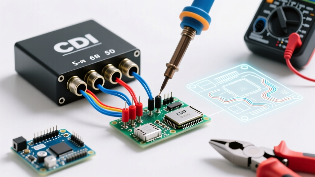
When rebuilding a small engine, motorcycle, ATV, or go-kart, the ignition system is often the most misunderstood subsystem. At the heart of this system is the Capacitor Discharge Ignition (CDI) module. Unlike traditional points-based or modern EFI systems, a CDI stores high-voltage energy in a capacitor and releases it in a microsecond burst to the ignition coil. Understanding the correct wiring diagram for CDI box configurations is critical; a single miswired pin can result in a dead engine, a melted stator, or a destroyed ignition coil.
In this comprehensive motor wiring tutorial, we will break down the anatomy of AC and DC CDI units, map out the industry-standard 5-pin and 6-pin pinouts, and provide actionable multimeter testing procedures to verify your harness before you ever hit the starter button.
AC vs. DC CDI Systems: Identifying Your Architecture
Before consulting any wiring diagram for CDI box applications, you must determine whether your engine utilizes an AC or DC ignition architecture. Mixing these up is the most common cause of aftermarket CDI failure.
AC CDI (Stator-Powered)
Common on 50cc to 150cc scooters (like the ubiquitous GY6 engine), pit bikes, and older 2-stroke dirt bikes. The AC CDI draws its primary power directly from the stator's dedicated ignition winding. It does not require a battery to run; in fact, many AC CDI engines can be kick-started with a completely dead or disconnected battery. Physically, AC CDI boxes are typically smaller (roughly 3.5 x 2.5 inches) and feature a single bullet connector or a 4-pin/5-pin plug.
DC CDI (Battery-Powered)
Found on larger ATVs, modern street bikes, and 200cc+ utility engines. A DC CDI draws 12V DC from the battery/rectifier system, steps it up internally using an inverter circuit, and then stores it in the capacitor. These units are generally larger (approx. 4.5 x 3 inches) and almost always use a 6-pin connector. Diagnostic Tip: If your engine requires a healthy 12V battery to spark, you have a DC CDI.
The Standard 5-Pin Wiring Diagram for CDI Box (GY6 / AC Style)
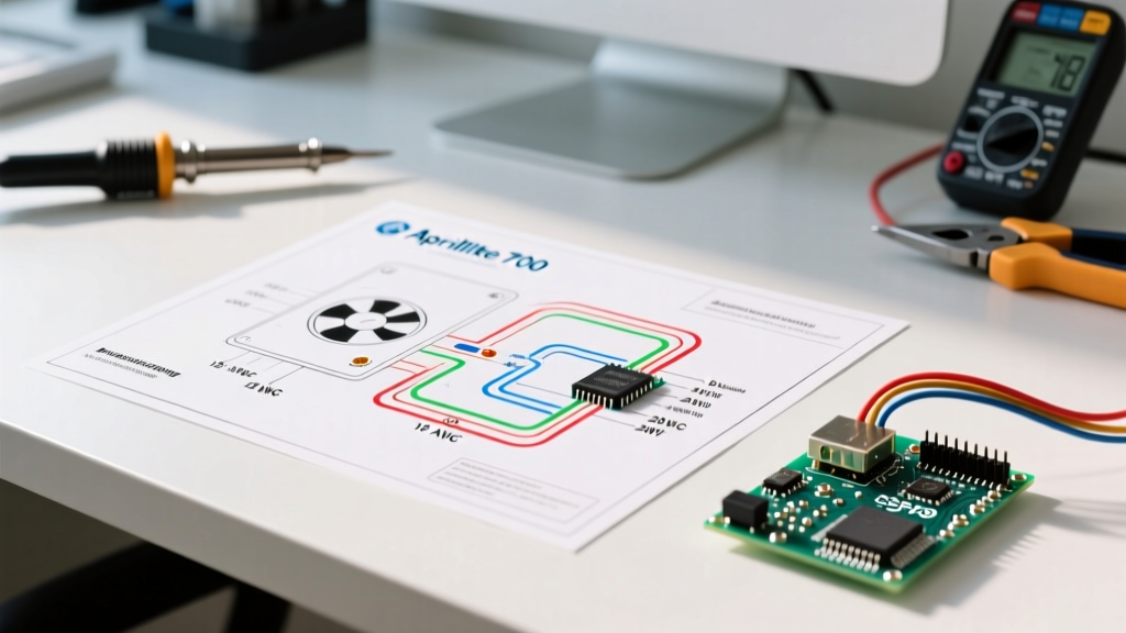
The 5-pin AC CDI is the most widely distributed ignition module in the global small engine market. While wire colors can vary slightly between Chinese manufacturing batches, the functional pinout remains remarkably consistent. Below is the definitive reference table for testing and wiring a 5-pin harness.
| Pin | Standard Wire Color | Function | Multimeter Test (Engine Cranking) |
|---|---|---|---|
| 1 | Black/White | Kill Switch (Ground to stop) | Continuity to ground when switch is OFF |
| 2 | Green | Chassis Ground | Continuity to battery/frame ground |
| 3 | Blue/White | Trigger / Pulse Coil Signal | 0.5V - 2.0V AC (Peak) |
| 4 | Black/Red | Stator AC Power Input | 100V - 400V AC (True-RMS) |
| 5 | Black/Yellow | High Voltage Out (to Coil) | N/A (Do not probe directly) |
⚠️ High Voltage Warning: Never attempt to back-probe Pin 5 (High Voltage Out) with a standard multimeter while cranking. The CDI outputs between 250V and 400V DC in microsecond pulses. This will instantly blow the fuse or destroy the logic board of a standard digital multimeter. Always test the primary and secondary sides of the ignition coil instead.
The 6-Pin CDI Box Wiring Diagram (DC / ATV Style)
The 6-pin DC CDI (often configured in a 2x3 or 4+2 layout) is standard on Honda CG/CB clones, TRX ATVs, and many utility motors. Because it relies on battery voltage, the wiring diagram for CDI box systems of this type includes a dedicated 12V feed and a more complex trigger circuit.
- Pin 1 (Red or Black/Red): 12V DC Power In. Must have 12.4V+ when the ignition key is ON. Sourced from the ignition switch, protected by a 10A fuse.
- Pin 2 (Green): Main Ground. Must have less than 0.05 ohms of resistance to the engine block.
- Pin 3 (Blue/Yellow or Blue/White): Trigger Coil Positive. Receives the pulse signal from the stator pickup.
- Pin 4 (Green/White or Yellow): Trigger Coil Negative / Signal Ground. Completes the trigger circuit back to the stator.
- Pin 5 (Black/White): Kill Circuit. Grounding this pin dumps the capacitor and halts spark.
- Pin 6 (Black/Yellow): High Voltage Output to the primary side of the ignition coil.
Step-by-Step Motor Wiring Tutorial: Building the Harness
When replacing a melted harness or wiring a custom motor swap, adhering to proper automotive electrical standards is non-negotiable. According to guidelines outlined in the National Electrical Code (NEC) regarding low-voltage automotive and mobile applications, wire gauge selection must account for both current draw and voltage drop over distance.
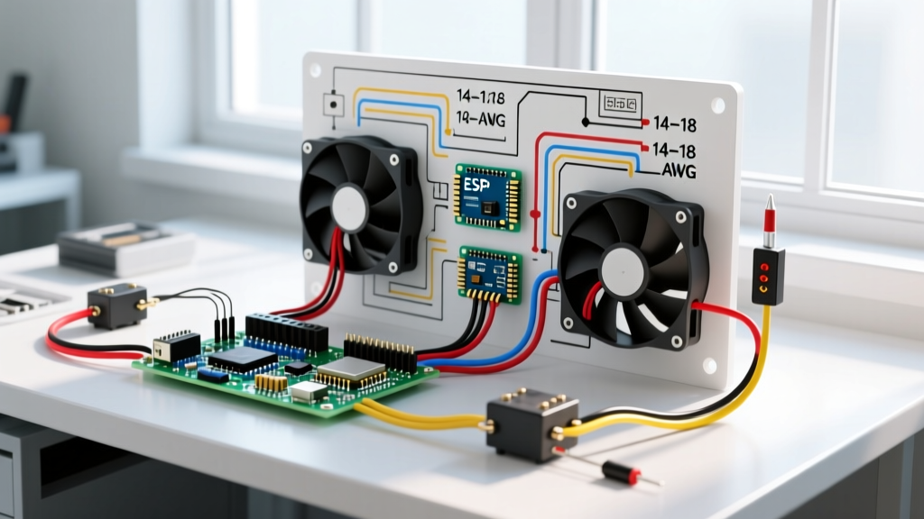
- Select the Right Wire: Use TXL (Cross-linked polyethylene) or GXL automotive wire. TXL is rated for 125°C and has a thin insulation wall, making it ideal for tight engine bays. Use 18 AWG for signal and trigger wires, 16 AWG for the stator AC feed, and 14 AWG for the 12V DC battery feed and main grounds.
- Terminate Properly: Abandon cheap vinyl crimps. Use adhesive-lined heat shrink butt splices (nylon insulated). Strip the wire, crimp with a ratcheting crimper, and apply heat until the adhesive seals the wire jacket.
- Weatherproof the Connector: Pack the CDI plug cavity with Permatex 22058 Dielectric Grease. This prevents moisture ingress, which causes galvanic corrosion on the brass pins—a primary failure point in off-road and marine environments.
Troubleshooting Edge Cases & Failure Modes
Even with a perfect wiring diagram for CDI box reference, electrical gremlins occur. Here are three advanced troubleshooting scenarios that stump most DIYers:
1. The "Phantom Spark" (Weak Orange Spark)
If your engine has spark, but it is weak, orange, and fails to jump a 3/8-inch gap, the issue is rarely the spark plug. It is usually a failing internal capacitor within the CDI or a weak stator magnet. To verify, consult capacitor discharge theory resources to understand dielectric breakdown. If the stator AC output (Pin 4 on a 5-pin) reads below 80V AC while kick-starting, the stator's ignition winding is failing, or the flywheel has lost magnetic flux.
2. The Kill Switch Short
Chinese-manufactured handlebar kill switches are notorious for internal corrosion. If the switch corrodes internally, it creates a parasitic path to ground on the Black/White wire, killing the spark. Pro-Tip: If you have no spark, unplug the Black/White kill wire from the CDI harness entirely. If the engine suddenly sparks, your CDI and stator are fine; your handlebar switch or tether lanyard is shorting out.
3. DC CDI Inverter Failure
If a 6-pin DC CDI receives 12V at Pin 1, has a solid ground, and receives a trigger signal, but outputs zero high voltage, the internal DC-to-DC step-up inverter has failed. This is common when a battery is severely sulfated and sends voltage spikes exceeding 16V into the CDI during hard cranking. Always test battery health before condemning a DC CDI.
2026 Market Snapshot: Replacement CDI Units
When sourcing replacements, avoid unbranded, ultra-cheap units that lack internal potting (epoxy resin used to protect against vibration). Here is what you should expect to pay in the current market:
- Generic GY6 5-Pin AC CDI: $12 - $18. Adequate for stock 50cc-150cc scooters. Look for units with visible epoxy sealing around the connector base.
- Performance Adjustable CDI (e.g., TrailMaster, SSR): $45 - $85. Features a built-in rev-limiter adjustment dial and advanced timing curves for modified engines.
- OEM Honda/Yamaha 6-Pin DC CDI: $140 - $220. Required for late-model ATVs with immobilizer or complex mapping. Never replace an OEM DC CDI with an aftermarket AC unit without completely rewiring the stator and harness.
For deeper diagnostics on stator and pickup coil resistance values specific to your exact engine model, always cross-reference your readings with the RM Stator Technical Documents database, which provides OEM-accurate ohm and voltage specifications for thousands of powersport vehicles.
Final Verification Checklist
Before plugging the CDI into the harness for the first time after a rewire, perform this 60-second checklist:
- Verify Pin 2 (Ground) has less than 0.05 ohms to the engine block.
- Confirm the Kill Switch wire is NOT grounded when the key is in the "ON" position.
- Ensure the High Voltage output wire is securely routed to the ignition coil and is not touching the exhaust header or frame.
- Check that all stator wires are secured away from the flywheel cooling fins.
By treating the wiring diagram for CDI box systems as a strict electrical blueprint rather than a vague suggestion, you ensure reliable, high-energy spark delivery and eliminate the most frustrating category of small-engine no-start diagnostics.