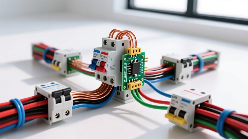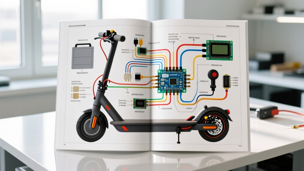

Why Generic Diagrams Fail: Trusting the OEM Owner's Manual
Diagnosing a dead 48V electric scooter requires more than guesswork; it demands a systematic approach using the manufacturer's documentation. While the internet is flooded with generic 'universal' 48V scooter wiring diagrams, relying on them is a primary cause of misdiagnosis and blown controllers. As of 2026, the majority of mid-tier and premium 48V scooters utilize advanced FOC (Field Oriented Control) sine-wave controllers rather than older square-wave models. These modern systems feature proprietary pinouts, integrated CAN-bus communication lines, and specific hall-sensor phasing that generic diagrams simply do not capture.
Your specific 48 volt electric scooter wiring diagram owner's manual is the ultimate source of truth. It provides the exact color-coding, pin assignments, and voltage thresholds required to safely trace a fault from the battery management system (BMS) to the hub motor. This guide will teach you how to read that OEM schematic and apply it to real-world troubleshooting scenarios.
Decoding the 48V Schematic: Key Nodes and Pinouts
Before taking a multimeter to your scooter, you must understand the primary nodes depicted in your owner's manual wiring diagram. A standard 48V OEM schematic will highlight the following critical junctions:
- Main Power Loop (Thick Red/Black): Carries the raw 48V (nominal 54.6V fully charged) from the battery BMS to the main contactor or controller.
- Ignition Switch Circuit (Thin Red/Orange): A low-current loop that triggers the controller's internal logic board and DC-DC converter.
- Hall Sensor Harness (6-Pin JST Connector): Provides 5V power, ground, and three phase-specific signal wires (usually Yellow, Green, Blue) to read rotor position.
- Throttle Potentiometer (3-Pin Connector): Supplies a 5V reference, ground, and a variable signal wire (typically White or Green).
- Brake Inhibit Switches: Normally-open or normally-closed circuits that cut power to the motor phase wires when engaged.
The Multimeter Matrix: Pinpointing 48V Scooter Faults
Using your OEM diagram, you can isolate faults by comparing expected voltages against actual readings. Always use a True-RMS multimeter, such as the Fluke 117 or Klein Tools MM400, and refer to Fluke's official multimeter guide for proper back-probing techniques to avoid piercing wire insulation.
| Symptom | Diagram Node to Check | Expected Voltage / State | Common Failure Mode |
|---|---|---|---|
| Completely dead, no display | Main BMS Output / Ignition Loop | 50V - 54.6V DC | Tripped BMS, blown main fuse, or faulty ignition switch. |
| Display on, motor won't spin | Brake Inhibit Switches | 5V (pulled high) or 0V (pulled low) depending on logic | Stuck brake lever sensor or severed inhibit wire. |
| Motor stutters or vibrates | Hall Sensor Signal Wires | 0V to 5V square wave while spinning wheel | Blown internal 5V regulator or damaged hall sensor. |
| Throttle unresponsive | Throttle Signal Wire | 0.8V (rest) to 4.2V (full twist) | Water ingress in throttle housing or broken wiper track. |
| Lights and horn dead | DC-DC Converter Output | 12.0V - 13.8V DC | Failed step-down converter or blown 12V accessory fuse. |
Advanced Tracing: Throttle Potentiometers and Brake Inhibits
The most common reason a 48V scooter 'turns on but won't go' is a fault in the low-voltage logic circuits, specifically the throttle or brake inhibit lines. Your owner's manual diagram will show whether your brake levers use a Normally Open (NO) or Normally Closed (NC) logic.
Testing the 3-Wire Throttle
Locate the throttle pinout on your diagram. Connect your multimeter's black probe to a known good chassis ground and the red probe to the signal wire. With the key on, the resting voltage should be between 0.8V and 1.1V. As you slowly twist the throttle, the voltage should climb smoothly to 4.2V - 4.5V. If the voltage jumps erratically or stays at 0V, the potentiometer's internal carbon track is damaged, or the 5V reference wire from the controller is severed.
Diagnosing Brake Inhibits
If the manual specifies a high-level brake inhibit, the controller expects to see 5V on the brake wire when the lever is released, and 0V when pulled. A stuck brake sensor will continuously feed 0V to the controller, keeping the motor phase MOSFETs disabled. Unplug the brake sensors at the main harness junction to rule out a mechanical switch failure.
Regenerative Braking and Phase Wire Diagnostics
Modern 2026 FOC controllers utilize the motor's phase wires (Thick Yellow, Green, Blue) for both propulsion and regenerative braking. If your scooter throws an 'Error 07' or 'Phase Fault' code on the dashboard, the diagram will direct you to the motor harness.
Disconnect the motor phase wires from the controller. Set your multimeter to continuity mode. Check for continuity between each phase wire and the motor casing (ground). Any reading below infinite resistance (OL) indicates a shorted stator winding or melted phase wire insulation inside the axle—a common failure point on high-torque 48V hub motors. Furthermore, check the resistance between the phase wires themselves; they should read nearly identical low-ohm values (typically 0.1 to 0.5 ohms). A discrepancy of more than 0.2 ohms between phases points to internal stator damage.
BMS Communication Protocols: UART and CAN-bus
Unlike older scooters where the battery simply supplied raw DC power, modern 48V systems feature 'smart' batteries that communicate with the controller and dashboard via UART or CAN-bus protocols. Your wiring diagram will show a 2-wire or 4-wire data plug (often a 5-pin Julet or Higo connector).
If your dashboard displays a 'Battery Communication Error' or shows an incorrect state-of-charge (SOC), the BMS data line is compromised. While you cannot read CAN-bus data with a standard multimeter, you can verify the physical layer. Check the diagram for the CAN-High and CAN-Low pins. With the system powered, CAN-High should sit around 2.5V to 3.5V, and CAN-Low around 1.5V to 2.5V. If both read 0V or 48V, the BMS communication IC has failed, or the data wire is pinched. For deep-dive knowledge on maintaining the lithium cells inside these smart packs, consult Battery University's guide on lithium-based battery longevity.
Safety Warning: A fully charged 48V scooter battery can output over 50 Amps continuously and hundreds of amps in a short-circuit scenario. DC arcs do not self-extinguish like AC arcs. Always disconnect the main battery lead and wait 5 minutes for the controller's internal capacitors to discharge before probing the phase wires or MOSFETs. Adhere to OSHA electrical safety standards when working with high-current DC systems.
Essential Tools for Diagram-Based Troubleshooting
To effectively execute the tests outlined in your owner's manual, you need the right equipment. Relying on cheap test lights or basic continuity testers will yield false positives on sensitive logic boards.
- True-RMS Digital Multimeter: Essential for accurately reading the PWM signals and low-voltage logic lines (e.g., Fluke 117).
- Back-Probe Pins: Thin, flexible pins that allow you to test connector terminals without piercing the wire insulation, which prevents future corrosion.
- Breakout Harnesses: Y-splitter cables specific to your controller's connectors (e.g., 3-pin JST-SM for throttles) allowing you to measure voltages while the system is fully connected and under load.
- Soldering Station with Fine Tips: For repairing severed hall sensor wires directly at the stator board, requiring precise temperature control (around 320°C) to avoid melting adjacent components.
By treating your 48 volt electric scooter wiring diagram owner's manual not just as a reference, but as a diagnostic roadmap, you can systematically eliminate variables, avoid unnecessary parts replacement, and safely restore your scooter to peak performance.