
Pre-Installation Load Calculations and Circuit Sizing
Planning an electric water heater installation requires more than just matching wire colors to terminals. Before pulling any cable through conduit, you must perform a precise load calculation. Understanding the exact wiring diagram for electric water heater configurations ensures compliance with NEC Article 422 and prevents catastrophic thermal runaway, melted insulation, or nuisance breaker tripping.
Electric storage water heaters are classified as continuous loads under the National Electrical Code (NEC) if they are expected to operate for three hours or more. Therefore, the branch circuit must be sized at 125% of the heater's maximum current draw. For a standard 40-gallon tank with 4500-watt elements operating at 240 volts, the math is straightforward but critical:
- Base Amperage: 4500W ÷ 240V = 18.75 Amps
- Continuous Load Multiplier: 18.75A × 1.25 = 23.43 Amps
- Required Breaker Size: The next standard breaker size above 23.43A is 25A or 30A. Industry standard practice defaults to a 30A double-pole breaker.
- Required Wire Gauge: 10 AWG copper (THHN/THWN-2) rated for 60°C or 75°C terminations.
Standard 240V Non-Simultaneous Wiring Diagram Breakdown
The vast majority of residential resistive water heaters utilize a non-simultaneous operation sequence. This means the upper and lower heating elements never draw power at the exact same time, which keeps the maximum amperage draw within the limits of a standard 30A circuit.
Expert Insight: Never wire a standard residential water heater for simultaneous operation unless the manufacturer explicitly provides a simultaneous wiring diagram and you have upgraded the service to a 50A or 60A double-pole breaker with 6 AWG wire. Doing so on a 30A circuit will instantly trip the breaker or melt the bus bars.
Tracing the Circuit Path
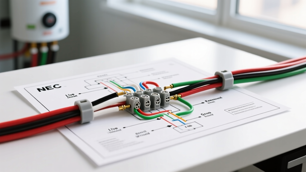
When analyzing the standard wiring diagram for electric water heater setups (such as those found on Rheem, Bradford White, and AO Smith resistive models), the current flows as follows:
- Line 1 (L1 - Black): Routes directly from the double-pole breaker to the upper thermostat, then hardwires directly to the left terminal of both the upper and lower heating elements.
- Line 2 (L2 - Red/White with black tape): Routes from the breaker to the upper thermostat. The upper thermostat acts as a diverter. When the upper tank temperature drops below the set point, L2 is switched to the upper element. Once the upper third of the tank is heated, the internal bi-metallic snap disc switches L2 down to the lower thermostat.
- Lower Thermostat: Receives L2 only when the upper thermostat is satisfied. It then switches power to the lower element to heat the bottom two-thirds of the tank.
- Ground (Bare/Green): Bonds directly to the green grounding screw on the tank jacket. No neutral wire is required or used in standard 240V resistive setups.
Wire Gauge, Breaker, and Conduit Matrix
Selecting the correct materials is paramount. Use the matrix below to plan your rough-in based on the specific element wattage stamped on your unit's data plate.
| Element Wattage | Voltage | Base Amperage | 125% Calc (Amps) | Min. Breaker Size | Min. Copper Wire (THHN) |
|---|---|---|---|---|---|
| 3800W | 240V | 15.8A | 19.7A | 20A or 25A | 12 AWG |
| 4500W | 240V | 18.75A | 23.4A | 25A or 30A | 10 AWG |
| 5500W | 240V | 22.9A | 28.6A | 30A | 10 AWG |
| 6000W | 240V | 25.0A | 31.2A | 35A or 40A | 8 AWG |
Modern Variations: Heat Pump and Smart Water Heaters
The 2026 residential market has seen a massive shift toward Hybrid Heat Pump Water Heaters (HPWH) driven by federal electrification rebates. According to the U.S. Department of Energy, HPWHs can be up to three times more energy-efficient than conventional electric resistance models. However, their internal wiring diagrams are fundamentally different.
The Neutral Wire Requirement
While a standard resistive heater only needs L1, L2, and Ground, many modern smart water heaters and HPWHs (like the Rheem ProTerra or AO Smith Voltex) feature 120V control boards, Wi-Fi modules, and defrost cycle logic. These components require a dedicated 120V leg. Consequently, the wiring diagram for electric water heater models with heat pumps often mandates a 12/3 or 10/3 NM-B cable (L1, L2, Neutral, Ground) or a 4-wire conduit setup. Failing to pull a neutral wire for a hybrid unit will result in a dead control board and a voided warranty. Always verify the specific unit's schematic before closing up the drywall.
Critical Edge Cases and Failure Modes
Even with the correct wiring diagram for electric water heater installations, field conditions introduce variables that cause premature failures. Watch for these specific edge cases:
- Undersized Torque on Terminal Lugs: The most common cause of melted wire insulation and tripped thermal cutoffs (ECO) is loose connections. Heating elements draw high amperage; a loose lug creates high resistance, generating intense localized heat. Always use a calibrated inch-pound torque screwdriver to tighten element and thermostat lugs to the manufacturer's specification (typically 15 to 20 in-lbs).
- Voltage Drop on Long Runs: If your panel is located more than 75 feet from the water heater, 10 AWG wire will suffer from voltage drop, causing the elements to run longer and hotter, degrading their lifespan. Upsize to 8 AWG copper for runs exceeding 75 feet to maintain a voltage drop below 3%.
- PEX Plumbing and Grounding Paths: In older homes with copper plumbing, the water pipes sometimes acted as a secondary ground path. In 2026, almost all new construction uses PEX (cross-linked polyethylene) piping, which is non-conductive. You must ensure the equipment grounding conductor (EGC) is continuous and properly bonded to the tank, as you can no longer rely on the plumbing system for fault clearing.
NEC Code Compliance Checklist
Before energizing the circuit, run through this compliance checklist based on the National Fire Protection Association's NEC guidelines and local amendments:
- Disconnecting Means: NEC 422.31 requires a means to disconnect the water heater. A standard double-pole breaker in the main panel qualifies if it is within sight of the heater or capable of being locked in the OFF position. If the panel is out of sight and lacks a lockout provision, a local 30A fused disconnect switch must be installed within sight of the appliance.
- Overcurrent Protection: Verify the breaker matches the 125% continuous load calculation. Do not use a 40A breaker on 10 AWG wire, even if the water heater data plate suggests a 'Max Fuse Size' of 40A; the wire ampacity must always dictate the breaker size to protect the cable from melting.
- GFCI/AFCI Requirements: While standard hardwired water heaters in dedicated spaces generally do not require GFCI protection under baseline NEC rules, local jurisdictions (especially in states with strict 2023/2026 adoptions) may mandate GFCI breakers for 240V appliances in garages, unfinished basements, or crawlspaces. Check with your local AHJ (Authority Having Jurisdiction).
- Working Clearance: Maintain a minimum 30-inch wide and 36-inch deep working space in front of the electrical panel and any local disconnects, as per NEC 110.26.
Final Commissioning Steps
Once the wiring is complete and the tank is 100% full of water (never energize an empty tank, or the elements will dry-fire and burn out in seconds), use a multimeter to verify 240V across the upper thermostat terminals. Set the upper thermostat to 120°F and the lower to 110°F to optimize efficiency and prevent scalding. For further efficiency standards and rebates applicable to modern installations, consult the ENERGY STAR water heater database. Proper planning and strict adherence to the wiring diagram ensures a safe, code-compliant installation that will last for the lifetime of the tank.