
Anatomy of a Modern 200-Amp Electrical Panel Diagram
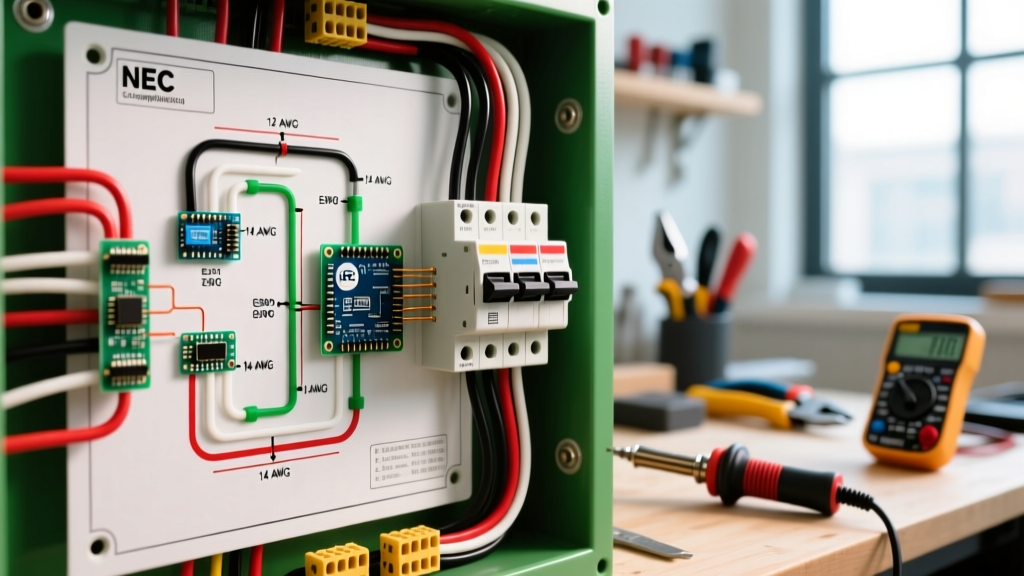
When you unroll a schematic or examine the label inside your service equipment, the electrical panel wiring diagram serves as the master blueprint for your home's power distribution. In 2026, with the proliferation of Level 2 EV chargers, solar inverters, and smart home subpanels, understanding these diagrams is no longer just for licensed electricians. Whether you are upgrading from a 100-amp to a 200-amp service or simply adding a dedicated circuit, misinterpreting the diagram can lead to catastrophic bus bar failures or code violations.
Modern load centers, such as the Square D HOM2448M125PGC (Homeline, 24-space, 125A main) or the Eaton BRP20B100, utilize plug-on neutral (PON) technology. This fundamentally changes the wiring diagram by eliminating the need for individual neutral pigtails on AFCI/GFCI breakers, routing the neutral directly through the breaker to the neutral bar. According to the National Fire Protection Association (NFPA), adhering strictly to the manufacturer's diagram is mandated by NEC Article 110.3(B).
Expert Note: Never assume all bus bars are energized equally. In split-phase 120/240V systems, alternate bus bar stabs carry opposite legs (Phase A and Phase B). A 240V breaker must span two adjacent stabs to draw from both legs simultaneously. Installing a 2-pole breaker on a panel that requires a specific spacing (like older Challenger panels) requires strict adherence to the panel's unique wiring diagram.
Decoding Standard Schematic Symbols
Electrical diagrams use standardized NEMA and IEC symbols. Below is a translation matrix for the most common symbols you will encounter when planning a panel upgrade.
| Symbol / Notation | Meaning | Panel Application & 2026 Context |
|---|---|---|
| Single Line with Slash | 1-Pole Breaker (120V) | Standard lighting/receptacles. Now heavily restricted by AFCI mandates in living spaces. |
| Double Line with Tie | 2-Pole Breaker (240V) | HVAC, EV chargers. Must feature an internal common trip mechanism. |
| Two Lines, One Stab | Tandem / Duplex Breaker | Two 120V circuits on one stab. Only permitted on CTL (Circuit Total Limiting) panels. |
| Circle with 'T' Inside | Thermal Overload / Trip | Indicates the bimetallic strip inside the breaker housing. |
| Wavy Line over Straight | GFCI / AFCI Protection | Dual-function breakers (e.g., Square D HOM120DF) required in kitchens, laundry, and bedrooms. |
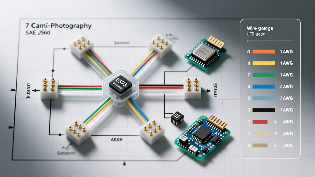
Breaker Sizing and Wire Gauge Matrix (2026 NEC Standards)
The most critical aspect of any electrical wiring diagram is matching the overcurrent protection device (OCPD) to the conductor ampacity. NEC Table 310.16 dictates these limits based on insulation temperature ratings. While THHN wire in conduit is rated for 90°C, the termination points on standard residential breakers are typically rated for 75°C. Therefore, the 75°C column governs your final ampacity.
| Breaker Rating | Copper Wire Gauge (NM-B / THHN at 75°C) | Max Continuous Load (80% Rule) | Typical 2026 Application |
|---|---|---|---|
| 15 Amp | 14 AWG | 12 Amps | General lighting (where AFCI allows 14 AWG) |
| 20 Amp | 12 AWG | 16 Amps | Kitchen small appliance, bathroom GFCI receptacles |
| 30 Amp | 10 AWG | 24 Amps | Dryers, water heaters, small RV outlets |
| 40 Amp | 8 AWG | 32 Amps | Level 2 EV Chargers (e.g., ChargePoint Home Flex) |
| 50 Amp | 6 AWG | 40 Amps | Electric ranges, heavy-duty workshop welders |
| 60 Amp | 4 AWG (or 6 AWG THHN in specific conditions) | 48 Amps | Subpanel feeds, Tesla Wall Connector (max config) |
The Torque Specification Mandate
A frequent failure mode in DIY panel work is loose terminal connections, leading to thermal runaway and melted bus bars. NEC 110.14(D) strictly requires the use of a calibrated torque screwdriver or torque wrench for terminals rated 14 AWG through 10 AWG. For a standard Square D Homeline breaker, the lug torque requirement is typically 35 in-lbs. Using a tool like the Klein Tools 69060 (4-70 in-lb range) ensures compliance and prevents arcing faults.
Step-by-Step: Tracing a 240V Circuit on the Diagram
When adding a high-draw appliance like a 40A EV charger, tracing the circuit on your electrical panel wiring diagram ensures you maintain phase balance. Here is the professional workflow:
- Identify the Main OCPD: Locate the main breaker on the schematic (e.g., 200A). Ensure your new 40A load does not exceed the panel's calculated demand load per NEC Article 220.
- Locate Adjacent Bus Stabs: Find two adjacent vertical stabs on the diagram. Verify they are on opposite phases (A and B). Most diagrams label phases with alternating colors or letters.
- Route the Hot Conductors: Connect the Black and Red (or Black and White with black tape) THHN wires to the dual-pole breaker terminals (e.g., Eaton BR240).
- Terminate the Ground: Route the bare copper or green wire to the equipment grounding bar. Never terminate a ground wire on the neutral bar in a subpanel.
- Verify Phase Balance: Update your panel schedule. If Phase A has 120A of continuous load and Phase B has 40A, place the new 240V breaker to balance the 120V single-pole loads as evenly as possible across both legs.
Subpanel Wiring Diagrams: The Neutral-to-Ground Bond
One of the most dangerous mistakes occurs when wiring a subpanel (e.g., for a detached garage or solar inverter). According to NEC 250.142(B), the neutral and ground must remain strictly isolated in any panel downstream of the main service disconnect.
When reading a subpanel wiring diagram, you will notice a green bonding screw or strap. In a main panel, this strap connects the neutral bar to the metal enclosure (ground). In a subpanel, this strap must be removed. If left intact, normal neutral return current will travel along the equipment grounding conductors and metal conduits, creating a severe shock hazard and potential electromagnetic interference with sensitive electronics.
Edge Cases: Tandem Breakers and CTL Rejection
Tandem (or duplex) breakers allow two 120V circuits to occupy a single panel space. However, you cannot simply insert them anywhere. Modern panels utilize a CTL (Circuit Total Limiting) bus bar design. The bus stab features a physical notch that rejects non-CTL tandem breakers. As detailed in Schneider Electric's technical documentation, forcing a non-CTL breaker onto a CTL bus bar damages the stab, leading to poor contact and overheating. Always check your panel's wiring diagram for the maximum number of circuits allowed (e.g., a 20-space/40-circuit panel allows tandems in specific designated spaces only).
Classified vs. Listed Breakers
Can you use an Eaton CL breaker in a Square D panel? The UL classification system allows certain breakers to be 'classified' for use in competitor panels, provided they undergo rigorous testing to UL safety standards. However, your local Authority Having Jurisdiction (AHJ) may still reject them if the panel manufacturer's wiring diagram explicitly forbids foreign breakers. Always default to the manufacturer's listed breakers (e.g., Square D QO for QO panels, Eaton BR for BR panels) to ensure warranty validity and code compliance.
Frequently Asked Questions
Why does my wiring diagram show a 'Switched Neutral'?
Switched neutrals are generally prohibited in standard residential AC wiring (NEC 404.2(B)) because they leave the appliance energized even when turned off, posing a lethal shock hazard during maintenance. If your diagram shows this, it is likely for a specific 240V appliance with an integrated contactor, not a standard branch circuit.
How do I read the 'AIC' rating on the diagram?
AIC (Ampere Interrupting Capacity) indicates the maximum short-circuit current the breaker can safely stop without exploding. Standard residential breakers are rated for 10,000 AIC. If your home is located very close to the utility transformer, your available fault current may exceed this, requiring 22,000 AIC or 42,000 AIC breakers as specified by the utility's service diagram.