
The Core Architecture of an E-Bike Controller
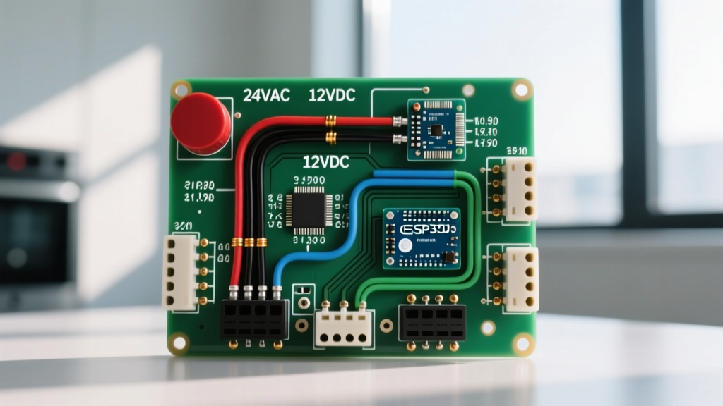
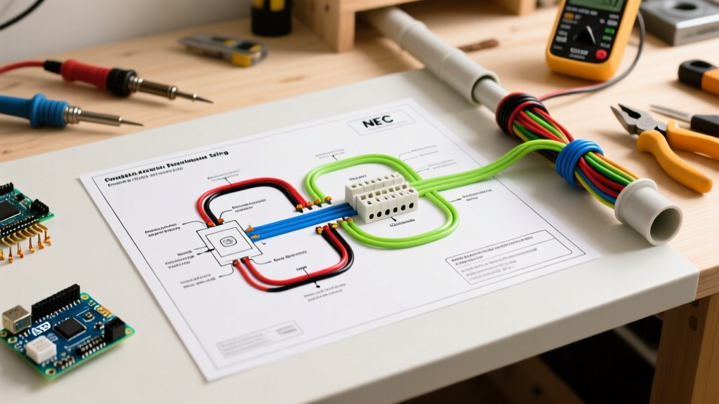
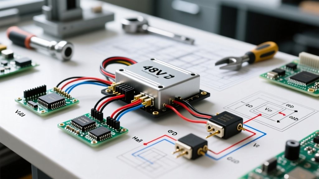
When converting a standard bicycle or troubleshooting a factory-built e-bike, the motor controller acts as the central nervous system. Interpreting an electric bicycle controller wiring diagram correctly is the difference between a smooth, reliable ride and a catastrophic MOSFET failure. Modern brushless DC (BLDC) controllers, such as the ubiquitous KT36/48SVPR or the high-end Grin Phaserunner, manage complex tasks including sinusoidal commutation, regenerative braking, and UART-based display communication.
As of 2026, the industry has largely standardized around color-coded wire harnesses for generic controllers, but the internal logic levels and connector types vary wildly. According to extensive field data from Grin Technologies, over 60% of DIY e-bike electrical failures stem from incorrect hall sensor wiring or improper phase wire sequencing, rather than component defects.
Standard 48V Controller Pinout & Wire Color Matrix
Below is the reference matrix for a standard 48V 22A (nominal) square-wave/sine-wave hybrid controller. Always verify your specific manufacturer's schematic, as Chinese generic models occasionally swap the blue and green hall sensor wires.
| Wire Color / Bundle | Function | Voltage / Signal Type | Connector Type (Typical) |
|---|---|---|---|
| Thick Red & Black | Main Battery Power (B+ / B-) | 36V - 52V DC | XT60 / XT90-S (Anti-spark) |
| Thick Yellow, Green, Blue | Motor Phase Wires (A, B, C) | High-Frequency PWM (up to 50V) | 4mm / 5mm Gold Bullet |
| 5-Pin Thin (Red, Blk, Yel, Grn, Blu) | Hall Effect Sensors | 5V DC (Red/Blk), Digital Pulse (Y/G/B) | SM-2.8mm or JST-SM |
| 3-Pin (Red, Blk, Wht/Grn) | Throttle Input | 5V, GND, 0.8V - 4.2V Analog | SM-2.8mm |
| 4-Pin (Red, Blk, Yel, Grn) | UART Display (SPTA Protocol) | 5V, GND, TX (3.3V/5V), RX | Higo / Waterproof 4-pin |
| 2-Pin (Grey / White) | E-Brake Cutoffs | Active Low (Pull to GND to stop) | SM-2.8mm |
The Safe Wiring Sequence (Preventing MOSFET Blowouts)
A common mistake among novices is connecting the battery first and probing the low-voltage signal wires while the system is live. This can induce voltage spikes that destroy the controller's internal 5V LDO (Low Dropout) voltage regulator. Follow this exact sequence:
- Secure the Phase Wires: Connect the thick Yellow, Green, and Blue motor phase wires. Ensure bullet connectors are fully seated. A loose phase wire under load will cause an arc, melting the connector and potentially sending inductive kickback voltage back into the controller's MOSFET bridge.
- Connect the Hall Sensors: Plug in the 5-pin hall sensor connector. Never force this plug; bending a pin will short the 5V line to the signal line, instantly frying the AMS1117-5.0 SMD regulator on the controller PCB.
- Wire the Peripherals: Connect the throttle, PAS (Pedal Assist Sensor), e-brakes, and display. Keep the main battery disconnected during this step.
- Final Power Connection: Connect the main battery lead. If using a standard XT60, you will hear a loud 'pop' and see a spark as the controller's internal capacitors charge. To prevent this contact pitting, use an XT90-S anti-spark connector or wire a pre-charge resistor circuit.
Hall Sensor Calibration & Phase Wire Matching
BLDC motors require precise timing to operate efficiently. The controller uses the hall sensors to determine the rotor's exact position before energizing the corresponding phase wire. If the motor stutters, draws excessive current (over 30A at no-load), or spins backward, your phase/hall combination is incorrect.
Method 1: The 'Learning' Wire (Auto-Calibration)
Many generic 48V controllers feature a single-loop white or grey 'learning' wire. With the rear wheel elevated off the ground:
- Plug the two ends of the learning wire together.
- Power on the controller. The motor will automatically begin to spin, cycle through hall/phase permutations, and lock onto the correct timing.
- Once the motor spins smoothly in the forward direction, unplug the learning wire. The controller saves this state to its non-volatile memory.
Method 2: Manual Trial and Error
High-end controllers like the Texas Instruments-based reference designs (detailed in TI's BLDC Application Notes) or the Grin Phaserunner do not use learning wires. Instead, they require software configuration via a USB-to-UART adapter. You must map the 120-degree or 60-degree hall sensor spacing in the configuration software, then run an automated phase-detection routine that measures back-EMF to align the commutation angle.
Edge Cases & Troubleshooting Common Wiring Faults
Expert Tip: Never use a standard automotive test light on e-bike signal wires. The incandescent bulb draws too much current and will short the fragile 5V logic lines. Always use a high-impedance digital multimeter (DMM).
Fault 1: Dead Display and No Throttle Response
Diagnosis: The 5V LDO regulator is likely blown. Test: Set your multimeter to DC Voltage. Back-probe the red wire on the throttle connector while the battery is connected. If you read 0V (instead of 5V), the regulator has failed. Fix: If you are proficient with SMD soldering, you can replace the AMS1117-5.0 chip for about $1. Otherwise, the controller must be replaced ($45-$60 for a generic unit).
Fault 2: Motor Stutters Under Load but Spins Fine on a Stand
Diagnosis: Phase wire connection failure or insufficient battery sag tolerance. Test: Inspect the bullet connectors between the controller and motor. Look for melted plastic or blackened brass. Under a 25A load, a poorly crimped connector introduces resistance, causing a voltage drop that confuses the controller's zero-crossing detection. Fix: Cut off the damaged connectors. Solder new 5mm gold bullets using a minimum 60W temperature-controlled soldering station. Use flux-core 60/40 leaded solder for the best capillary action.
Fault 3: Pedal Assist (PAS) Engages Erratically or Not at All
Diagnosis: Misaligned PAS magnet ring or reversed signal polarity. Test: The PAS sensor requires a precise 1mm to 3mm air gap from the magnet ring. Use a feeler gauge to verify the gap. Furthermore, use an oscilloscope or a multimeter with a frequency setting to check the signal wire. You should see a square wave pulsing between 0V and 5V as the pedals turn. If the voltage stays static at 5V, the sensor is either too far from the magnets or wired backward (VCC and GND swapped).
Upgrading Connectors for Long-Term Reliability
The weakest point in any electric bicycle controller wiring diagram is the connector hardware. The cheap, white SM-2.8mm plastic connectors shipped with 90% of aftermarket kits are notorious for vibrating loose and causing intermittent signal loss. For a professional-grade build, cut off the SM connectors and solder JST-SM 2.54mm pitch connectors for all low-voltage signal wires. For the main battery discharge lead, always use an Anderson Powerpole 45A or an Amass XT90-S. According to battery safety guidelines outlined by Battery University, ensuring low-resistance, high-amperage connections is critical to preventing thermal runaway events at the battery-to-controller junction.
Summary Checklist for First Power-Up
- Verify battery voltage matches controller rating (e.g., 54.6V max for a 48V nominal system).
- Ensure the rear wheel is elevated off the ground.
- Confirm all e-brake levers are disengaged (active-low circuits will prevent motor spin if brakes are pulled).
- Check that the throttle is at the zero position (most controllers have a High-Pedal Protection fault that triggers if the throttle is engaged during power-on).
- Power on and listen for the controller's initialization beep (if equipped) or check the display for error codes (e.g., Error 07 or 08 typically indicates a hall sensor short/open).