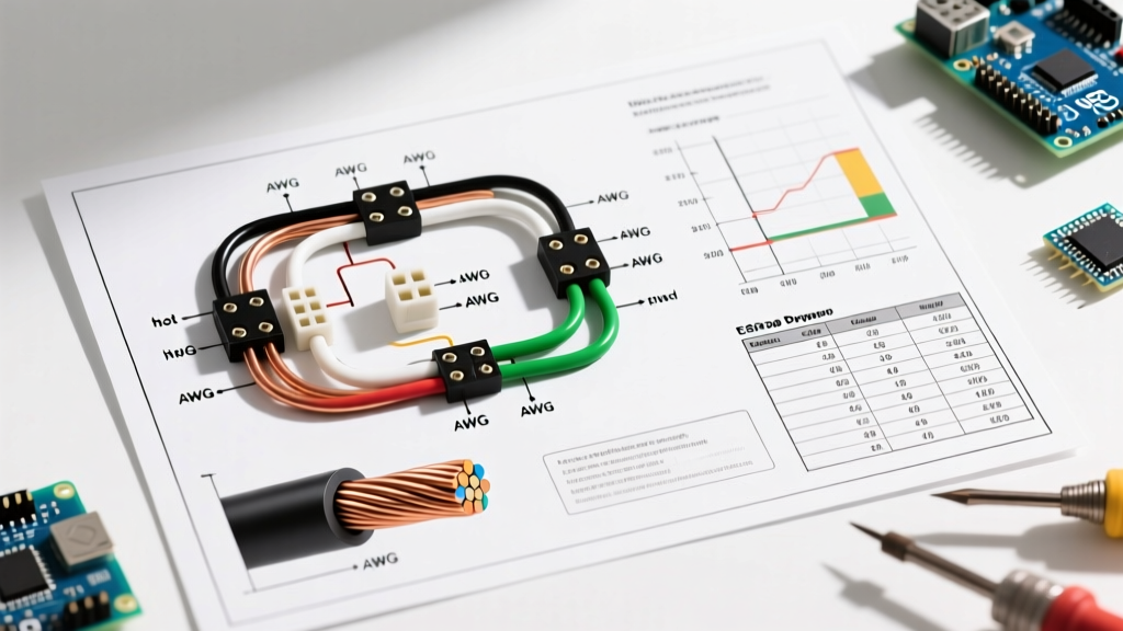

The Critical Role of Wire Gauge and Color Codes in Schematics
When interpreting electric wiring diagrams, the physical representation of conductors is just as vital as the logical flow of the circuit. A schematic might show you how a relay triggers a contactor, but the wiring diagram dictates the physical reality: which color wire connects to which terminal, and whether that wire can safely handle the thermal load. Misinterpreting these details doesn't just lead to a tripped breaker; it risks catastrophic arc faults, insulation meltdown, and severe electrical fires.
According to the National Fire Protection Association (NFPA), improper wire sizing and misidentified conductors remain leading causes of electrical failures in both residential and commercial settings. This comprehensive reference guide bridges the gap between theoretical diagrams and field-ready execution, focusing strictly on North American NEC standards, AWG physics, and edge-case color coding.
Anatomy of Conductor Representation in Electric Wiring Diagrams
In professional electric wiring diagrams, wires are rarely drawn as simple, uniform lines. Drafters use specific line weights, hash marks, and alphanumeric tags to convey critical physical properties. A thick line might indicate a 2/0 AWG feeder, while a thin line represents a 14 AWG control circuit. Furthermore, you will often see notations like 3/C #12 AWG THHN next to a conduit run. This translates to: three conductors, 12-gauge thickness, with Thermoplastic High Heat-resistant Nylon-coated insulation.
Expert Insight: Never assume the line thickness on a printed diagram perfectly correlates to wire gauge unless a legend explicitly states so. Always look for the alphanumeric wire tags (e.g., W1, W2) and cross-reference the bill of materials (BOM) or wire schedule on the drawing's title block.
Standard AC Wire Color Codes (NEC Compliance)
The National Electrical Code (NEC) Article 310.12 establishes strict identification requirements for grounded (neutral) and grounding conductors, while Article 210.4(D) and 215.12(C) dictate phase coloring for multi-wire branch circuits and feeders. When reading electric wiring diagrams for commercial or industrial panels, you must know the voltage class, as color codes shift between 120/208V and 277/480V systems.
AC Power Color Matrix
| System Voltage | Phase A (L1) | Phase B (L2) | Phase C (L3) | Neutral (Grounded) | Equipment Ground |
|---|---|---|---|---|---|
| 120/208V (Wye) | Black | Red | Blue | White | Green / Bare |
| 277/480V (Wye) | Brown | Orange | Yellow | Gray | Green / Bare |
| 240V (Split-Phase) | Black | Red | N/A | White | Green / Bare |
The High-Leg Delta Edge Case
One of the most dangerous edge cases in North American electric wiring diagrams is the 120/240V High-Leg Delta system, commonly found in older commercial buildings. In this configuration, Phase B (the high leg) measures 208V to ground, rather than the standard 120V. NEC Article 110.15 strictly mandates that this high leg be identified by the color Orange. If a diagram shows an orange wire connected to a standard 120V breaker, stop immediately—connecting a 120V load to the high leg will instantly destroy the equipment and pose a severe shock hazard.
Decoding Wire Gauge (AWG) and Ampacity
The American Wire Gauge (AWG) system is logarithmic and, counterintuitively, inverse: as the gauge number increases, the physical diameter and current-carrying capacity (ampacity) decrease. Understanding this is crucial when verifying the wire schedule on electric wiring diagrams.
The ampacity of a wire is not a fixed number; it depends heavily on the insulation temperature rating (60°C, 75°C, or 90°C) and the termination temperature limits of the connected equipment. Per NEC 110.14(C), you must size the overcurrent protection based on the lowest temperature rating in the circuit, which is typically 60°C for residential breakers under 100A, even if the THHN wire itself is rated for 90°C.
Copper Wire Sizing and Breaker Matching Chart
| AWG Size | Diameter (inches) | Circular Mils (CM) | Max Ampacity (60°C) | Max Ampacity (75°C) | Standard Breaker Size |
|---|---|---|---|---|---|
| 14 AWG | 0.0641 | 4,110 | 15A | 20A | 15A |
| 12 AWG | 0.0808 | 6,530 | 20A | 25A | 20A |
| 10 AWG | 0.1019 | 10,380 | 30A | 35A | 30A |
| 8 AWG | 0.1285 | 16,510 | 40A | 50A | 40A |
| 6 AWG | 0.1620 | 26,240 | 55A | 65A | 60A |
| 4 AWG | 0.2043 | 41,740 | 70A | 85A | 70A / 80A |
| 2 AWG | 0.2576 | 66,360 | 95A | 115A | 100A |
Voltage Drop: The Invisible Diagram Killer
A common failure mode when executing electric wiring diagrams is ignoring the physical distance of the wire run. The NEC recommends (and many local jurisdictions mandate) that voltage drop be limited to 3% for branch circuits and 5% overall for feeder and branch circuits combined. If a diagram specifies 12 AWG wire for a 20A motor located 150 feet from the panel, the wire is legally safe from melting, but the motor will experience severe voltage drop, leading to overheating and premature failure.
To calculate voltage drop for single-phase AC circuits, use the following formula:
VD = (2 × K × I × L) / CM
- VD: Voltage Drop
- K: Direct Current Constant (12.9 for Copper, 21.2 for Aluminum)
- I: Current in Amperes
- L: One-way length of the wire in feet
- CM: Circular Mils of the conductor (found in the chart above)
According to the Occupational Safety and Health Administration (OSHA), ensuring proper voltage delivery is a core component of electrical safety, as undervoltage conditions cause motors to draw excessive current, bypassing thermal overloads and creating fire hazards.
DC and Control Circuit Color Codes
Not all electric wiring diagrams deal with AC mains power. Industrial control panels, solar arrays, and telecom racks rely heavily on DC power, which follows an entirely different set of color conventions. Mixing up AC and DC color codes is a frequent cause of catastrophic short circuits.
- Standard DC (Automotive/Solar): Red is Positive (+), Black is Negative/Ground (-).
- Telecom DC (-48V Systems): Red is Negative (-48V), Black is Ground/Return, and Yellow is Alarm/Control.
- Control Circuits (24VDC): Blue is often used for DC positive, with Blue/White stripe for DC negative, per IEC standards often adopted in global PLC panels.
International Clashes: IEC vs. NEC in Imported Machinery
When working with electric wiring diagrams for imported machinery (e.g., Siemens, ABB, or KUKA robotics), you will encounter IEC 60446 color codes. European equipment uses Brown, Black, and Gray for AC phases, Blue for Neutral, and Green/Yellow for Earth Ground. If you are integrating a 480V IEC machine into a US 480V facility, the brown/black/gray wires map to the US brown/orange/yellow phases. Always verify the diagram's origin standard before terminating connections. The Electrical Safety Foundation International (ESFI) frequently highlights the dangers of assuming uniform color codes across international equipment borders.
Pro Tips for Tracing Diagrams in the Field
- Use Phase Tape: If you are pulling 277/480V wire, the insulation might all be black or gray due to supply constraints. You must use colored phasing tape at every termination and splice point to match the diagram's color code requirements.
- Verify Stranded vs. Solid: Diagrams for high-vibration environments (like HVAC compressors or marine applications) will specify stranded wire (e.g., THWN). Never substitute solid wire, as vibration will cause work-hardening and eventual conductor snapping.
- Check the Grounding Symbol: In schematics, a standard earth ground symbol (three descending horizontal lines) means connection to the grounding electrode system. A chassis ground symbol (lines descending at an angle) means connection to the equipment enclosure. Confusing the two in electric wiring diagrams compromises the fault-current path.
Frequently Asked Questions
Can I use white wire for a hot leg in a switch loop?
Yes, but NEC Article 200.7(C)(2) requires that you permanently re-identify the white wire with black or red tape at every point where it is visible and accessible. On electric wiring diagrams, this is usually noted as 'WHT (BLK)' to indicate a re-identified neutral acting as a hot conductor.
Why does my diagram show aluminum wire for a 100A feeder?
Aluminum is highly cost-effective for large feeders (typically 2 AWG or larger). However, aluminum has a higher resistance and expands/contracts more than copper. If the diagram specifies aluminum, you must use anti-oxidant paste (like Noalox) and torque the lugs to the manufacturer's exact inch-pound specifications to prevent high-resistance arcing faults.
What does a dashed line mean on a wiring diagram?
A dashed or dotted line typically indicates a mechanical linkage between components (like a ganged breaker where one handle trips two separate poles) or a shielded cable's drain wire. It does not represent an electrical current path.